Skip to content

SkyNex Academy · Arduino

Arduino Course

48 lessons, from your first blinking LED to motors and sensors, in the order of a classic Arduino starter kit. Every lesson shows the circuit, the wiring and how the code works, step by step. Press Open in SkyNex Lab to build and run it in your browser: no board needed.

Getting started

What is Arduino?

Arduino is a small, cheap computer on one board (a microcontroller) that you program from your PC. It reads inputs (buttons, sensors) and controls outputs (LEDs, motors, displays). It was made in Italy in 2005 for students, and it is open source: anyone may build and improve it.

How a program (sketch) works

  • setup() runs once when the board starts: set up the pins.
  • loop() then runs again and again, for ever.
  • Pins are digital (HIGH / LOW) or analog (A0–A5 read 0–1023). Pins with a ~ can make PWM.

Two ways to follow the course

  1. In the browser: open a lesson in the free SkyNex Lab. The code compiles with the real Arduino compiler and runs on a virtual Arduino Uno. Sign in (free) to run code.
  2. With a real board: install the Arduino IDE from arduino.cc, connect the Uno with USB, choose Tools → Board → Arduino Uno and the port, paste the lesson code and press Upload. Build the same circuit on a breadboard.

Most lessons use a 220 Ω resistor in series with each LED on a real board. The Lab does not need it, but your board does.

Get the parts in our shop →

Part 1 · First steps: LEDs, sound and the Serial Monitor

Your first programs: switch outputs on and off, make sequences and timing, and let the Arduino talk to your computer.

Lesson 2Hello from the Serial Monitor

Open in SkyNex Lab →
Circuit of the lesson “Hello from the Serial Monitor” in SkyNex Lab

You will learn: Sending text and numbers from the Arduino to your computer.

How the code works

  1. 1Serial.begin(9600) starts the USB serial link at 9600 baud (bits per second).
  2. 2Serial.println() sends a line of text; the Serial Monitor shows it.
  3. 3A counter goes up by 1 every half second and is printed each time.
  4. 4Test it: press Run and watch the Serial Monitor under the circuit.
Show the code
// print messages to the Serial Monitor (9600 baud)

int counter = 0;

void setup() {
  Serial.begin(9600);
  Serial.println("Hello from Sky Nex Electronics!");
}

void loop() {
  counter++;
  Serial.print("Loop number: ");
  Serial.println(counter);
  delay(500);
}

Try this

  • Print the time since the start with millis().
  • Count down from 10 and print “Lift off!”.

Lesson 3Flowing LEDs (running light)

Open in SkyNex Lab →
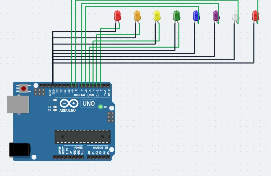
Circuit of the lesson “Flowing LEDs (running light)” in SkyNex Lab

You will learn: Driving many outputs with a for loop.

Parts and wiring

  • ●Arduino Uno (USB to your computer)
  • ●LED: Anode (+) → pin 2, GND → GND
  • ●LED: Anode (+) → pin 3, GND → GND
  • ●LED: Anode (+) → pin 4, GND → GND
  • ●LED: Anode (+) → pin 5, GND → GND
  • ●LED: Anode (+) → pin 6, GND → GND
  • ●LED: Anode (+) → pin 7, GND → GND
  • ●LED: Anode (+) → pin 8, GND → GND
  • ●LED: Anode (+) → pin 9, GND → GND

How the code works

  1. 1The pins 2 to 9 are set as outputs with one for loop.
  2. 2A second for loop lights each LED for 100 ms and switches it off again.
  3. 3A third loop runs back the other way, so the light bounces from end to end.
Show the code
// Eight LEDs on pins 2 to 9 light one after the other: a running light.
// A for loop saves us from writing 8 times the same lines.

const int FIRST = 2, COUNT = 8;

void setup() {
  for (int i = 0; i < COUNT; i++) pinMode(FIRST + i, OUTPUT);
}

void loop() {
  // left to right
  for (int i = 0; i < COUNT; i++) {
    digitalWrite(FIRST + i, HIGH);
    delay(100);
    digitalWrite(FIRST + i, LOW);
  }
  // and back
  for (int i = COUNT - 2; i > 0; i--) {
    digitalWrite(FIRST + i, HIGH);
    delay(100);
    digitalWrite(FIRST + i, LOW);
  }
}

Try this

  • Change the speed.
  • Leave the LEDs on so the bar fills up, then empties.

Lesson 4Traffic light

Open in SkyNex Lab →
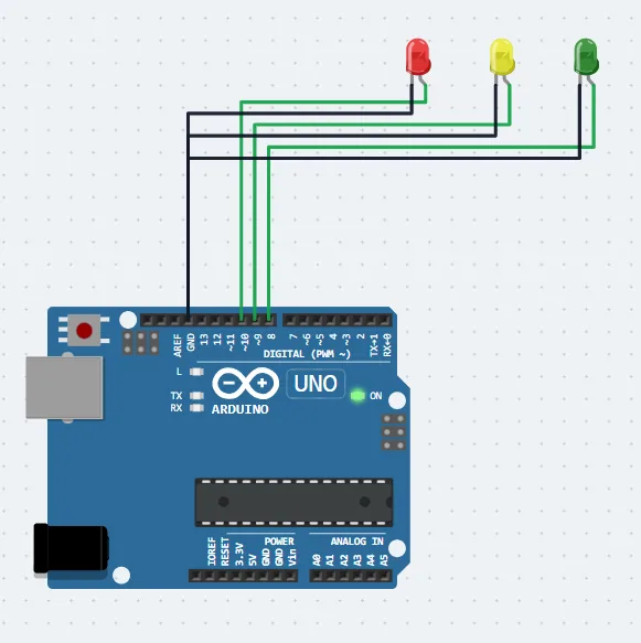
Circuit of the lesson “Traffic light” in SkyNex Lab

You will learn: Sequences and timing with three LEDs.

Parts and wiring

  • ●Arduino Uno (USB to your computer)
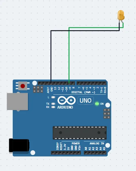
  • ●LED: Anode (+) → pin 10, GND → GND
  • ●LED: Anode (+) → pin 9, GND → GND
  • ●LED: Anode (+) → pin 8, GND → GND

How the code works

  1. 1Three LEDs on pins 10 (red), 9 (yellow) and 8 (green) are outputs.
  2. 2light(pin, ms) switches on only the chosen LED, then waits.
  3. 3loop() runs green for 4 s, yellow for 1.5 s and red for 4 s, over and over.
Show the code
// a traffic light with 3 LEDs (red 10, yellow 9, green 8)

const int RED = 10, YELLOW = 9, GREEN = 8;

void setup() {
  pinMode(RED, OUTPUT);
  pinMode(YELLOW, OUTPUT);
  pinMode(GREEN, OUTPUT);
}

void light(int pin, unsigned long ms) {
  digitalWrite(RED, pin == RED);
  digitalWrite(YELLOW, pin == YELLOW);
  digitalWrite(GREEN, pin == GREEN);
  delay(ms);
}

void loop() {
  light(GREEN, 4000);
  light(YELLOW, 1500);
  light(RED, 4000);
}

Try this

  • Show red and yellow together before green, as many countries do.
  • Add a pedestrian button that makes the light turn red sooner.

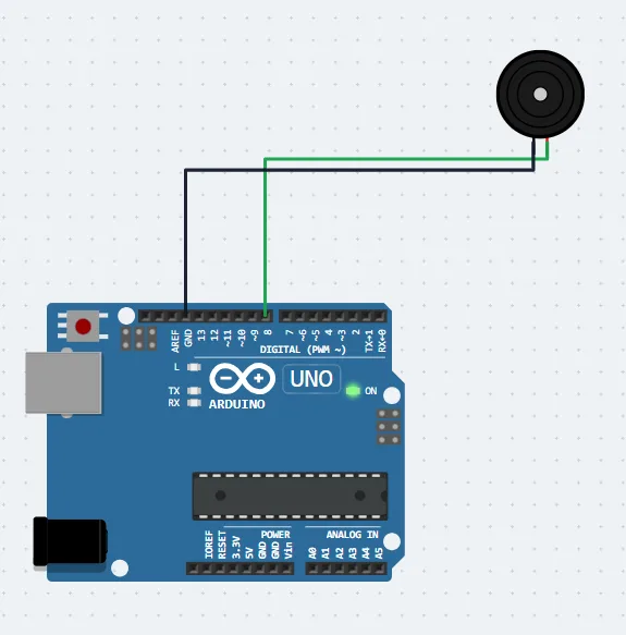
Lesson 5Active buzzer: beep alarm

Open in SkyNex Lab →
Circuit of the lesson “Active buzzer: beep alarm” in SkyNex Lab

You will learn: Making sound by switching a pin on and off quickly.

Parts and wiring

  • ●Arduino Uno (USB to your computer)
  • ●Buzzer: Signal → pin 8, GND → GND

How the code works

  1. 1A tone is a pin that goes HIGH and LOW very fast: 250 µs + 250 µs = 2000 times a second (2 kHz).
  2. 2beep(ms) repeats that until the time is over, measured with millis().
  3. 3loop() makes two short beeps, then a pause.
Show the code
// An active buzzer beeps by itself when it gets power. Here we make the sound with
// the pin (pin 8): switch it on and off 2000 times a second for a short beep.

const int BUZZER = 8;

void beep(int ms) {
  long end = millis() + ms;
  while (millis() < end) {
    digitalWrite(BUZZER, HIGH);
    delayMicroseconds(250);   // 250 µs HIGH + 250 µs LOW = 2000 Hz
    digitalWrite(BUZZER, LOW);
    delayMicroseconds(250);
  }
}

void setup() {
  pinMode(BUZZER, OUTPUT);
}

void loop() {
  beep(200);      // beep …
  delay(200);     // … pause
  beep(200);
  delay(1000);    // longer pause: "beep-beep … beep-beep"
}

Try this

  • Change 250 to 500 µs: the beep is lower (1 kHz).
  • Make an SOS: · · · — — — · · ·

Part 2 · Buttons, knobs and PWM

Reading inputs: buttons, switches and potentiometers, and using PWM to dim LEDs, mix colours and play notes.

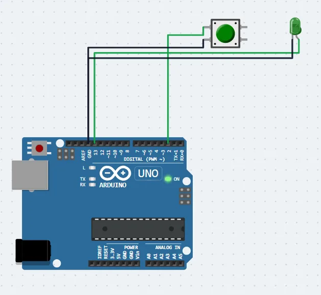
Lesson 6Button controls an LED

Open in SkyNex Lab →
Circuit of the lesson “Button controls an LED” in SkyNex Lab

You will learn: Reading a digital input with the internal pull-up resistor.

Parts and wiring

  • ●Arduino Uno (USB to your computer)
  • ●Pushbutton: Signal → pin 2, GND → GND
  • ●LED: Anode (+) → pin 13, GND → GND

How the code works

  1. 1pinMode(2, INPUT_PULLUP) turns on a resistor inside the chip, so the pin reads HIGH when the button is not pressed.
  2. 2The button connects the pin to GND: pressed = LOW.
  3. 3if (digitalRead(2) == LOW) the LED is switched on, else off.
Show the code
// press a button on pin 2 to light the LED on pin 13
// Wiring: button between pin 2 and GND (we use the internal pull-up resistor)

const int BUTTON_PIN = 2;
const int LED_PIN = 13;

void setup() {
  pinMode(BUTTON_PIN, INPUT_PULLUP);
  pinMode(LED_PIN, OUTPUT);
}

void loop() {
  bool pressed = digitalRead(BUTTON_PIN) == LOW; // LOW means pressed with INPUT_PULLUP
  digitalWrite(LED_PIN, pressed ? HIGH : LOW);
}

Try this

  • Make the LED light when the button is NOT pressed.
  • Make each press toggle the LED (on, off, on …).

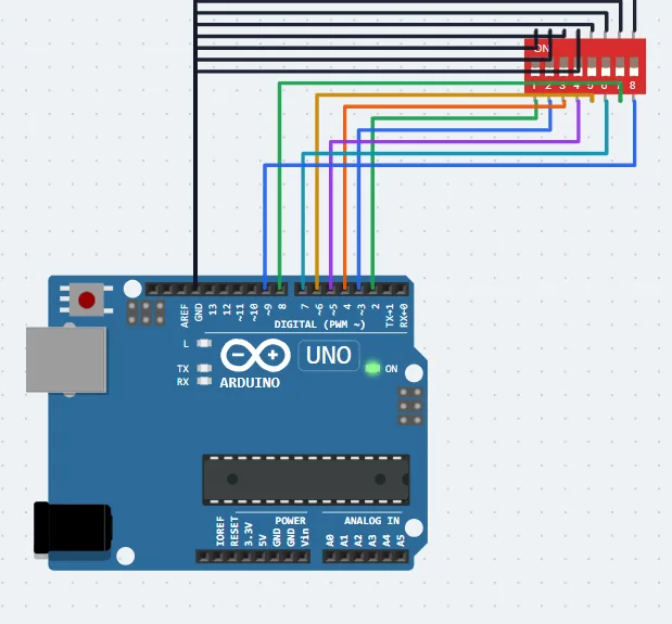
Lesson 7DIP switch to a binary number

Open in SkyNex Lab →
Circuit of the lesson “DIP switch to a binary number” in SkyNex Lab

You will learn: Reading many inputs at once and counting in binary.

Parts and wiring

  • ●Arduino Uno (USB to your computer)
  • ●DIP switch (8): Switch 1 → pin 2, Switch 2 → pin 3, Switch 3 → pin 4, Switch 4 → pin 5, Switch 5 → pin 6, Switch 6 → pin 7, Switch 7 → pin 8, Switch 8 → pin 9, GND → GND

How the code works

  1. 1Eight switches on pins 2 to 9 use INPUT_PULLUP: a switch that is ON pulls its pin LOW.
  2. 2Each switch is one bit: switch 1 = 1, switch 2 = 2, switch 3 = 4 … switch 8 = 128.
  3. 3value |= 1 << i sets the bit of every switch that is ON.
  4. 4Whenever the number changes, the program prints it in binary and in decimal.
  5. 5Test it: press Run and click the switches.
Show the code
// Eight DIP switches make an 8-bit binary number (switch 1 = 1, switch 8 = 128).
// Switches on pins 2 to 9 with INPUT_PULLUP: ON pulls the pin LOW.

byte last = 255;

void setup() {
  Serial.begin(9600);
  for (byte p = 2; p <= 9; p++) pinMode(p, INPUT_PULLUP);
}

void loop() {
  byte value = 0;
  for (byte i = 0; i < 8; i++) {
    if (digitalRead(2 + i) == LOW) value |= 1 << i;
  }
  if (value != last) {
    Serial.print("Binary ");
    for (int i = 7; i >= 0; i--) Serial.print((value >> i) & 1);
    Serial.print(" = ");
    Serial.println(value);
    last = value;
  }
}

Try this

  • Find the switches for 5, 100 and 255.
  • Show the number on the LCD.

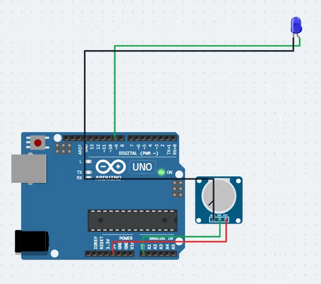
Lesson 8Potentiometer dims an LED

Open in SkyNex Lab →
Circuit of the lesson “Potentiometer dims an LED” in SkyNex Lab

You will learn: Analog input (analogRead) and PWM output (analogWrite).

Parts and wiring

  • ●Arduino Uno (USB to your computer)
  • ●Potentiometer: Wiper → A0, VCC → 5V, GND → GND
  • ●LED: Anode (+) → pin 9, GND → GND

How the code works

  1. 1analogRead(A0) turns 0–5 V into a number from 0 to 1023.
  2. 2map() scales it to 0–255, the range of analogWrite.
  3. 3analogWrite(9, …) dims the LED with PWM: the pin switches very fast, and the time HIGH sets the brightness.
Show the code
// read a potentiometer on A0 and dim an LED on pin 9 (PWM)

void setup() {
  Serial.begin(9600);
  pinMode(9, OUTPUT);
}

void loop() {
  int raw = analogRead(A0);              // 0 to 1023
  int brightness = map(raw, 0, 1023, 0, 255);
  analogWrite(9, brightness);            // 0 to 255
  Serial.print("Value: ");
  Serial.println(raw);
  delay(100);
}

Try this

  • Print the reading to the Serial Monitor.
  • Make the LED brighter when you turn the knob the other way.

Lesson 9Breathing LED (PWM)

Open in SkyNex Lab →
Circuit of the lesson “Breathing LED (PWM)” in SkyNex Lab

You will learn: Smooth brightness changes with analogWrite.

Parts and wiring

  • ●Arduino Uno (USB to your computer)
  • ●LED: Anode (+) → pin 9, GND → GND

How the code works

  1. 1analogWrite(9, value) with value from 0 to 255 sets the brightness.
  2. 2A for loop goes up from 0 to 255, a second one comes back down.
  3. 3A short delay in each step makes the breathing slow and smooth.
Show the code
// Fade an LED up and down smoothly with PWM.
// analogWrite gives 0 (off) to 255 (full brightness) on pins with a ~ mark.
const int LED = 9;

void setup() {
  pinMode(LED, OUTPUT);
}

void loop() {
  for (int b = 0; b <= 255; b += 5) {   // brighter
    analogWrite(LED, b);
    delay(15);
  }
  for (int b = 255; b >= 0; b -= 5) {   // dimmer
    analogWrite(LED, b);
    delay(15);
  }
}

Try this

  • Breathe faster or slower.
  • Make two LEDs breathe in opposite directions.

Lesson 10Colours with an RGB LED

Open in SkyNex Lab →
Circuit of the lesson “Colours with an RGB LED” in SkyNex Lab

You will learn: Mixing colours from red, green and blue.

Parts and wiring

  • ●Arduino Uno (USB to your computer)
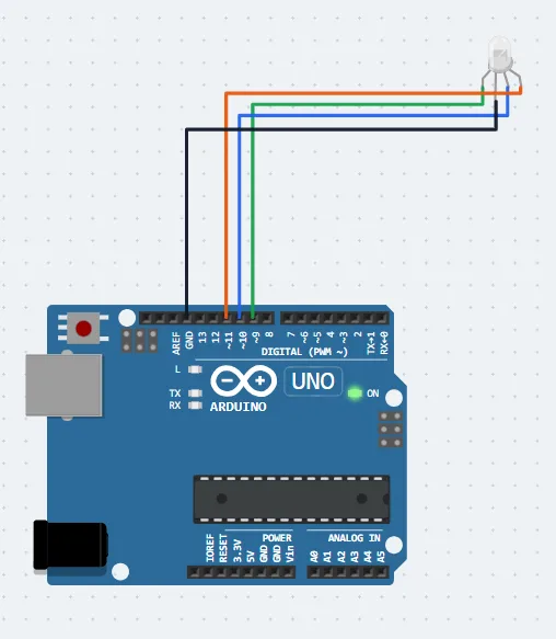
  • ●RGB LED: Red → pin 9, Green → pin 10, Blue → pin 11, GND → GND

How the code works

  1. 1An RGB LED is three LEDs in one: red, green and blue, each on a PWM pin.
  2. 2analogWrite on each pin sets how much of each colour you add.
  3. 3Red + green = yellow, red + blue = purple, all three = white.
Show the code
// mix colours with an RGB LED (red 9, green 10, blue 11)

void color(int r, int g, int b) {
  analogWrite(9, r);
  analogWrite(10, g);
  analogWrite(11, b);
}

void setup() {}

void loop() {
  color(255, 0, 0);   delay(700);  // red
  color(0, 255, 0);   delay(700);  // green
  color(0, 0, 255);   delay(700);  // blue
  color(255, 160, 0); delay(700);  // orange
  color(160, 0, 255); delay(700);  // purple
}

Try this

  • Make orange (lots of red, a little green).
  • Fade slowly through all the colours.

Lesson 11LED bar graph with a potentiometer

Open in SkyNex Lab →
Circuit of the lesson “LED bar graph with a potentiometer” in SkyNex Lab

You will learn: Showing a measured value as a level.

Parts and wiring

  • ●Arduino Uno (USB to your computer)
  • ●Slide potentiometer: Wiper → A0, VCC → 5V, GND → GND
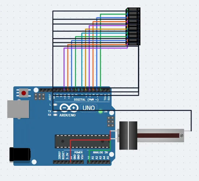
  • ●LED bar graph (10): LED 1 → pin 2, LED 2 → pin 3, LED 3 → pin 4, LED 4 → pin 5, LED 5 → pin 6, LED 6 → pin 7, LED 7 → pin 8, LED 8 → pin 9, LED 9 → pin 10, LED 10 → pin 11, GND → GND

How the code works

  1. 1The slider is read on A0 (0–1023).
  2. 2map() turns that into a number of LEDs, 0 to 10.
  3. 3A for loop switches on the first LEDs and switches off the rest.
Show the code
// Move the slide potentiometer: the LED bar graph shows the level (0-10 LEDs).
const int SLIDER = A0;
const int FIRST_LED = 2;   // bar graph LEDs on pins 2..11
const int COUNT = 10;

void setup() {
  for (int i = 0; i < COUNT; i++) pinMode(FIRST_LED + i, OUTPUT);
  Serial.begin(9600);
}

void loop() {
  int value = analogRead(SLIDER);                // 0..1023
  int lit = map(value, 0, 1023, 0, COUNT);        // 0..10 LEDs
  for (int i = 0; i < COUNT; i++) {
    digitalWrite(FIRST_LED + i, i < lit ? HIGH : LOW);
  }
  Serial.println(lit);
  delay(50);
}

Try this

  • Show the level the other way round.
  • Blink the last LED when the level is full.

Lesson 12Passive buzzer: play a melody

Open in SkyNex Lab →
Circuit of the lesson “Passive buzzer: play a melody” in SkyNex Lab

You will learn: tone() and noTone() to play notes.

Parts and wiring

  • ●Arduino Uno (USB to your computer)
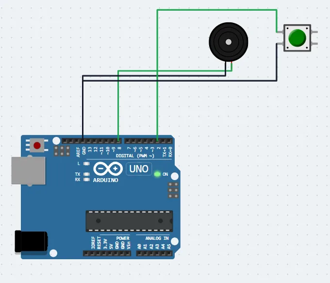
  • ●Buzzer: Signal → pin 8, GND → GND
  • ●Pushbutton: Signal → pin 2, GND → GND

How the code works

  1. 1tone(pin, frequency, duration) makes a square wave of that frequency: 262 Hz is the note C.
  2. 2The array notes[] holds the scale C D E F G A B C (262 to 523 Hz).
  3. 3When the button (pin 2) is pressed, a for loop plays the 8 notes one after the other.
Show the code
// press the button (pin 2) to play a short melody on the buzzer (pin 8)

const int BUZZER = 8;
const int BUTTON = 2;
int notes[] = {262, 294, 330, 349, 392, 440, 494, 523};

void setup() {
  pinMode(BUTTON, INPUT_PULLUP);
}

void loop() {
  if (digitalRead(BUTTON) == LOW) {
    for (int i = 0; i < 8; i++) {
      tone(BUZZER, notes[i], 180);
      delay(220);
    }
  }
}

Try this

  • Play the scale backwards.
  • Change the notes to play a short song.

Part 3 · Measuring like an engineer

See what really happens in your circuit with a multimeter and an oscilloscope: volts, amps, ohms and PWM signals.

Lesson 13Ohm’s law with two multimeters

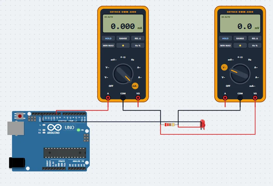
Open in SkyNex Lab →
Circuit of the lesson “Ohm’s law with two multimeters” in SkyNex Lab

You will learn: Measuring current and voltage, and checking V = I × R.

Parts and wiring

  • ●Arduino Uno (USB to your computer)
  • ●LED: GND → GND
  • ●Between the parts: Digital multimeter COM → Resistor 1, Resistor 2 → LED A, Digital multimeter VΩ → Resistor 1, Digital multimeter COM → Resistor 2

How the code works

  1. 1Pin 9 lights an LED through a 220 Ω resistor: 3 s on, 1.5 s off.
  2. 2The left multimeter is in the circuit (A and COM): it measures the current, about 12 mA.
  3. 3The right multimeter is across the resistor (VΩ and COM): it measures the voltage on it.
  4. 4Divide the volts by the amps and you get about 220, the resistor’s value. That is Ohm’s law.
  5. 5Click the meter dials to try other ranges, and press HOLD, REL and MIN MAX.
Show the code
// Ohm's law: V = I x R.
// Pin 9 lights an LED through a 220 ohm resistor. The left meter is IN the circuit
// (A and COM) and shows the current; the right meter (VΩ and COM) shows the voltage
// across the resistor. Check: volts / amps = 220.
// Click the dials to try other ranges, or press REL, HOLD and MIN MAX.

void setup() {
  pinMode(9, OUTPUT);
}

void loop() {
  digitalWrite(9, HIGH);   // LED on: about 12 mA flows
  delay(3000);
  digitalWrite(9, LOW);    // LED off: 0 mA
  delay(1500);
}

Try this

  • Predict the current with a 1 kΩ resistor, then change it and measure.
  • Measure the voltage across the LED as well and add the two voltages.

Lesson 14PWM on the oscilloscope

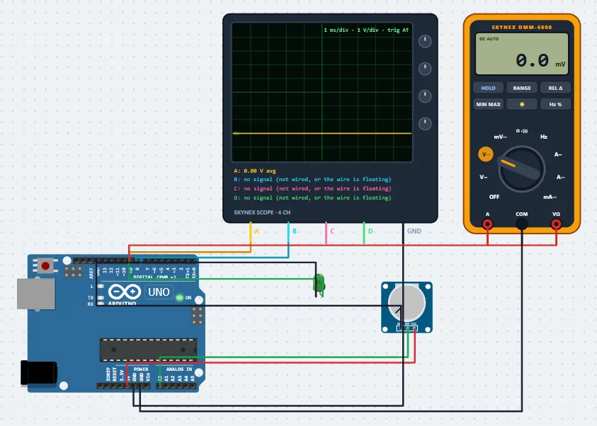
Open in SkyNex Lab →
Circuit of the lesson “PWM on the oscilloscope” in SkyNex Lab

You will learn: Seeing a PWM signal and its average voltage.

Parts and wiring

  • ●Arduino Uno (USB to your computer)
  • ●Potentiometer: Wiper → A0, VCC → 5V, GND → GND
  • ●LED: Anode (+) → pin 9, GND → GND

How the code works

  1. 1analogWrite(9, value) makes a square wave on pin 9 (about 490 Hz); its HIGH time sets the brightness.
  2. 2Turning the potentiometer changes the duty cycle from 0 % to 100 %.
  3. 3Oscilloscope channel A shows the PWM wave; channel B shows a 1 kHz tone from pin 8.
  4. 4The multimeter reads the average voltage: 5 V × duty cycle.
  5. 5Test it: press Run, turn the potentiometer and watch the wave get wider or narrower.
Show the code
// Measuring with instruments: turn the potentiometer (A0) to change the PWM on pin 9.
// Oscilloscope channel A shows the PWM square wave (about 490 Hz), channel B a 1 kHz tone on pin 8.
// The multimeter on pin 9 shows the average voltage: 5 V x duty cycle.

void setup() {
  pinMode(9, OUTPUT);
  tone(8, 1000);
}

void loop() {
  analogWrite(9, analogRead(A0) / 4);   // 0..1023 -> 0..255
  delay(20);
}

Try this

  • Read the frequency of channel B on the scope, then change the tone.
  • Find the potentiometer position that gives 2.5 V.

Part 4 · Displays

Showing numbers, text and pictures: 7-segment displays, LCDs, an OLED screen, an LED matrix and NeoPixels.

Lesson 15One 7-segment digit: count 0 to 9

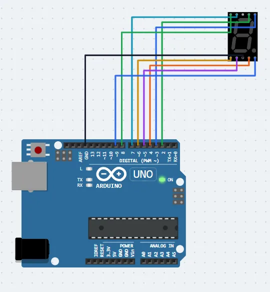
Open in SkyNex Lab →
Circuit of the lesson “One 7-segment digit: count 0 to 9” in SkyNex Lab

You will learn: How a 7-segment display shows numbers.

Parts and wiring

  • ●Arduino Uno (USB to your computer)
  • ●7-segment display: Segment A → pin 2, Segment B → pin 3, Segment C → pin 4, Segment D → pin 5, Segment E → pin 6, Segment F → pin 7, Segment G → pin 8, Segment DP → pin 9, GND → GND

How the code works

  1. 1Each of the 7 bars (a to g) is an LED on its own pin (2 to 8).
  2. 2A table (array) stores which bars light for each digit, one bit per bar.
  3. 3show(n) reads the bits of DIGITS[n] and switches each segment on or off.
Show the code
// A 7-segment display has 7 LED bars (a to g) and a dot. Segments a–g are on pins 2–8.
// A table says which segments light for each digit (1 = on).

const byte DIGITS[10] = {
  // gfedcba
  0b0111111, // 0
  0b0000110, // 1
  0b1011011, // 2
  0b1001111, // 3
  0b1100110, // 4
  0b1101101, // 5
  0b1111101, // 6
  0b0000111, // 7
  0b1111111, // 8
  0b1101111, // 9
};

void show(int n) {
  for (int s = 0; s < 7; s++) digitalWrite(2 + s, (DIGITS[n] >> s) & 1);
}

void setup() {
  for (int s = 0; s < 8; s++) pinMode(2 + s, OUTPUT);
}

void loop() {
  for (int n = 0; n <= 9; n++) {
    show(n);
    delay(700);
  }
}

Try this

  • Count down from 9 to 0.
  • Add the letters A, b, C, d, E, F to count in hex.

Lesson 16Button counter on a 7-segment display

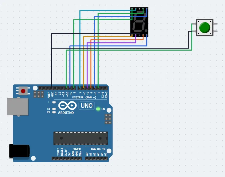
Open in SkyNex Lab →
Circuit of the lesson “Button counter on a 7-segment display” in SkyNex Lab

You will learn: Counting events and debouncing a button.

Parts and wiring

  • ●Arduino Uno (USB to your computer)
  • ●7-segment display: Segment A → pin 2, Segment B → pin 3, Segment C → pin 4, Segment D → pin 5, Segment E → pin 6, Segment F → pin 7, Segment G → pin 8, Segment DP → pin 9, GND → GND
  • ●Pushbutton: Signal → pin 10, GND → GND

How the code works

  1. 1The button is read with INPUT_PULLUP: pressed = LOW.
  2. 2The count only goes up when the button changes from released to pressed (an edge), not while it is held.
  3. 3A 20 ms delay ignores the bounce of the contacts.
Show the code
// Each press of the button (pin 10) adds 1. The 7-segment display (a–g on pins 2–8)
// shows the count 0 to 9. Debounce: count only when the button changes from
// released to pressed.

const byte DIGITS[10] = { 0b0111111, 0b0000110, 0b1011011, 0b1001111, 0b1100110, 0b1101101, 0b1111101, 0b0000111, 0b1111111, 0b1101111 };
const int BUTTON = 10;
int count = 0;
bool wasPressed = false;

void show(int n) {
  for (int s = 0; s < 7; s++) digitalWrite(2 + s, (DIGITS[n] >> s) & 1);
}

void setup() {
  for (int s = 0; s < 8; s++) pinMode(2 + s, OUTPUT);
  pinMode(BUTTON, INPUT_PULLUP);   // pressed = LOW
  show(0);
}

void loop() {
  bool pressed = digitalRead(BUTTON) == LOW;
  if (pressed && !wasPressed) {    // a new press
    count = (count + 1) % 10;
    show(count);
  }
  wasPressed = pressed;
  delay(20);                       // ignore contact bounce
}

Try this

  • Add a second button that counts down.
  • Reset to 0 after a long press.

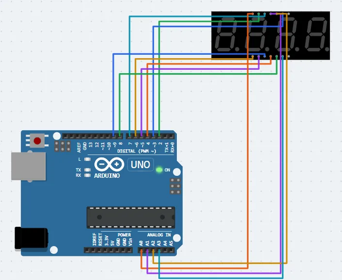
Lesson 174-digit 7-segment counter

Open in SkyNex Lab →
Circuit of the lesson “4-digit 7-segment counter” in SkyNex Lab

You will learn: Multiplexing: four digits with only twelve wires.

Parts and wiring

  • ●Arduino Uno (USB to your computer)
  • ●7-segment display (4 digits): Segment A → pin 2, Segment B → pin 3, Segment C → pin 4, Segment D → pin 5, Segment E → pin 6, Segment F → pin 7, Segment G → pin 8, Segment DP → pin 9, Digit 1 → A0, Digit 2 → A1, Digit 3 → A2, Digit 4 → A3

How the code works

  1. 1Segments A–G and DP are shared by all four digits (pins 2–9); each digit has its own pin (A0–A3).
  2. 2Only one digit is on at a time: the program shows digit 1, then 2, 3 and 4, each for 3 ms.
  3. 3It switches so fast that your eyes see all four digits lit together.
  4. 4Every 100 ms the counter goes up by 1, from 0000 to 9999.
Show the code
// Counts 0000 to 9999 on a 4-digit common-cathode display.
// Segments A..G, DP on pins 2..9; digits 1..4 on A0..A3 (LOW = digit on).
// Only one digit is on at a time; switching fast makes all four look lit.

const byte SEG[8] = {2, 3, 4, 5, 6, 7, 8, 9};
const byte DIG[4] = {A0, A1, A2, A3};
const byte FONT[10] = {0x3F, 0x06, 0x5B, 0x4F, 0x66, 0x6D, 0x7D, 0x07, 0x7F, 0x6F}; // bit 0 = A

unsigned int value = 0;
unsigned long lastCount = 0;

void showDigit(byte d, byte n) {
  for (byte k = 0; k < 4; k++) digitalWrite(DIG[k], HIGH);       // all digits off
  for (byte s = 0; s < 8; s++) digitalWrite(SEG[s], (FONT[n] >> s) & 1);
  digitalWrite(DIG[d], LOW);                                     // this digit on
  delay(3);
}

void setup() {
  for (byte s = 0; s < 8; s++) pinMode(SEG[s], OUTPUT);
  for (byte d = 0; d < 4; d++) pinMode(DIG[d], OUTPUT);
}

void loop() {
  if (millis() - lastCount >= 100) {
    lastCount = millis();
    value = (value + 1) % 10000;
  }
  showDigit(0, value / 1000);
  showDigit(1, value / 100 % 10);
  showDigit(2, value / 10 % 10);
  showDigit(3, value % 10);
}

Try this

  • Make it count seconds instead.
  • Show the potentiometer value (0–1023).

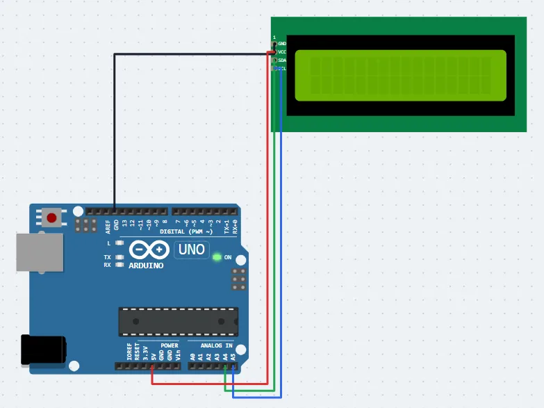
Lesson 18Text on an LCD 16x2 (I2C)

Open in SkyNex Lab →
Circuit of the lesson “Text on an LCD 16x2 (I2C)” in SkyNex Lab

You will learn: Using a library and the I2C bus (only 2 wires: SDA and SCL).

Parts and wiring

  • ●Arduino Uno (USB to your computer)
  • ●LCD 16x2 (I2C): SDA → A4, SCL → A5, VCC → 5V, GND → GND

How the code works

  1. 1#include <LiquidCrystal_I2C.h> adds the LCD library; the display is at address 0x27.
  2. 2lcd.init() and lcd.backlight() start it; lcd.print() writes text.
  3. 3lcd.setCursor(column, row) chooses where to write; line 2 shows the seconds since start (millis() / 1000).
Show the code
// show text and a counter on a 16x2 LCD with I2C backpack (address 0x27)
// Wiring: SDA -> A4, SCL -> A5, VCC -> 5V, GND -> GND
#include <Wire.h>
#include <LiquidCrystal_I2C.h>

LiquidCrystal_I2C lcd(0x27, 16, 2);

void setup() {
  lcd.init();
  lcd.backlight();
  lcd.setCursor(0, 0);
  lcd.print("Sky Nex Lab");
}

void loop() {
  lcd.setCursor(0, 1);
  lcd.print("Seconds: ");
  lcd.print(millis() / 1000);
  delay(250);
}

Try this

  • Write your name on line 1.
  • Show minutes and seconds (mm:ss).

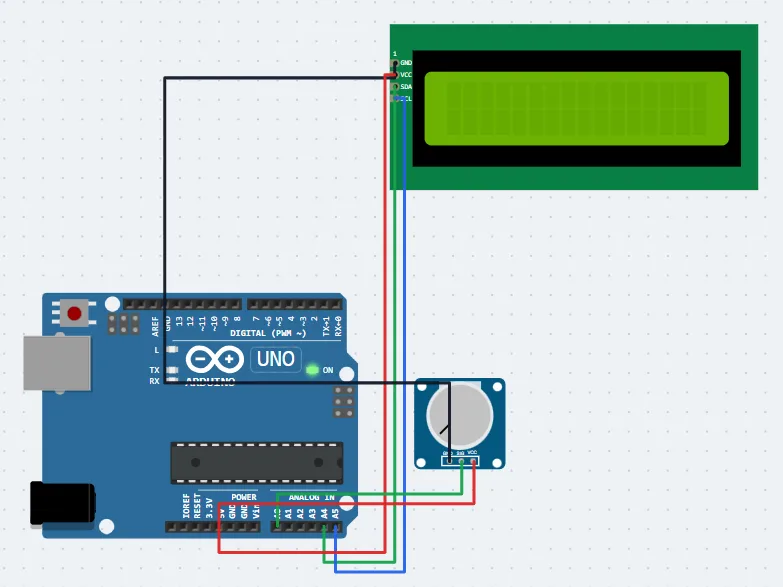
Lesson 19Voltmeter on an LCD

Open in SkyNex Lab →
Circuit of the lesson “Voltmeter on an LCD” in SkyNex Lab

You will learn: Converting an analog reading into volts.

Parts and wiring

  • ●Arduino Uno (USB to your computer)
  • ●LCD 16x2 (I2C): SDA → A4, SCL → A5, VCC → 5V, GND → GND
  • ●Potentiometer: Wiper → A0, VCC → 5V, GND → GND

How the code works

  1. 1analogRead(A0) gives 0–1023 for 0–5 V.
  2. 2volts = reading × 5.0 / 1023 (use 5.0, not 5, so the result has decimals).
  3. 3lcd.print(volts, 2) shows 2 decimals; the extra spaces wipe old digits.
Show the code
// Turn the potentiometer (A0): the LCD shows the voltage from 0.00 to 5.00 V.
// analogRead gives 0 to 1023 for 0 to 5 V, so volts = reading × 5.0 / 1023.

#include <Wire.h>
#include <LiquidCrystal_I2C.h>

LiquidCrystal_I2C lcd(0x27, 16, 2);

void setup() {
  lcd.init();
  lcd.backlight();
  lcd.print("SkyNex Voltmeter");
}

void loop() {
  int raw = analogRead(A0);
  float volts = raw * 5.0 / 1023;
  lcd.setCursor(0, 1);
  lcd.print("U = ");
  lcd.print(volts, 2);   // 2 decimals
  lcd.print(" V    ");   // spaces wipe old digits
  delay(200);
}

Try this

  • Also show the reading (0–1023) on line 1.
  • Show a warning when the voltage is above 4 V.

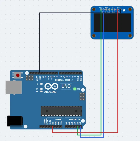
Lesson 20Graphics on an OLED screen

Open in SkyNex Lab →
Circuit of the lesson “Graphics on an OLED screen” in SkyNex Lab

You will learn: Drawing text and shapes on a 128 × 64 pixel screen.

Parts and wiring

  • ●Arduino Uno (USB to your computer)
  • ●SSD1306 OLED (I2C): SDA → A4, SCL → A5, VCC → 5V, GND → GND

How the code works

  1. 1The SSD1306 OLED uses I2C (SDA A4, SCL A5) at address 0x3C, with the Adafruit SSD1306 and GFX libraries.
  2. 2setTextSize, setCursor and println write text; drawRect draws a frame.
  3. 3Nothing appears until display.display() sends the picture to the screen.
  4. 4In loop() the ball is erased and drawn again 6 pixels further on: a simple animation.
Show the code
// draw text and shapes on a 128x64 SSD1306 OLED (I2C address 0x3C)
#include <Wire.h>
#include <Adafruit_GFX.h>
#include <Adafruit_SSD1306.h>

Adafruit_SSD1306 display(128, 64, &Wire, -1);

void setup() {
  display.begin(SSD1306_SWITCHCAPVCC, 0x3C);
  display.clearDisplay();
  display.setTextSize(2);
  display.setTextColor(SSD1306_WHITE);
  display.setCursor(10, 5);
  display.println("Sky Nex");
  display.drawRect(5, 30, 118, 28, SSD1306_WHITE);
  display.display();
}

int x = 8;
void loop() {
  display.fillRect(6, 31, 116, 26, SSD1306_BLACK);
  display.fillCircle(x, 44, 8, SSD1306_WHITE);
  display.display();
  x = x >= 112 ? 16 : x + 6;
  delay(50);
}

Try this

  • Make the ball bounce back instead of jumping to the start.
  • Show the potentiometer value as a bar.

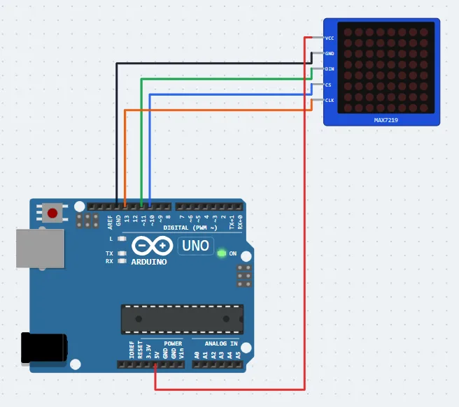
Lesson 218x8 LED dot matrix

Open in SkyNex Lab →
Circuit of the lesson “8x8 LED dot matrix” in SkyNex Lab

You will learn: Drawing pictures on a matrix with a driver chip (MAX7219).

Parts and wiring

  • ●Arduino Uno (USB to your computer)
  • ●LED dot matrix 8x8 (MAX7219): DIN → pin 11, CS → pin 10, CLK → pin 13, VCC → 5V, GND → GND

How the code works

  1. 1The MAX7219 drives 64 LEDs with only 3 Arduino pins (DIN, CS, CLK).
  2. 2Each row is one byte: 1 bits are lit LEDs. A heart is 8 bytes.
  3. 3The program switches between a big and a small heart: it beats.
Show the code
// A heart beats on an 8x8 LED matrix driven by a MAX7219 (DIN 11, CS 10, CLK 13).
// Each command is two bytes: the register (1-8 = rows) then the data.

const byte DIN = 11, CS = 10, CLK = 13;
const byte BIG[8]   = {0x00, 0x66, 0xFF, 0xFF, 0xFF, 0x7E, 0x3C, 0x18};
const byte SMALL[8] = {0x00, 0x00, 0x24, 0x7E, 0x7E, 0x3C, 0x18, 0x00};

void send(byte reg, byte data) {
  digitalWrite(CS, LOW);
  shiftOut(DIN, CLK, MSBFIRST, reg);
  shiftOut(DIN, CLK, MSBFIRST, data);
  digitalWrite(CS, HIGH);           // the MAX7219 takes the word when CS goes HIGH
}

void draw(const byte rows[8]) {
  for (byte r = 0; r < 8; r++) send(r + 1, rows[r]);
}

void setup() {
  pinMode(DIN, OUTPUT);
  pinMode(CS, OUTPUT);
  pinMode(CLK, OUTPUT);
  digitalWrite(CS, HIGH);
  send(0x09, 0x00);   // no digit decoding: we send raw dots
  send(0x0A, 0x08);   // brightness
  send(0x0B, 0x07);   // scan all 8 rows
  send(0x0F, 0x00);   // display test off
  send(0x0C, 0x01);   // wake up
}

void loop() {
  draw(BIG);
  delay(400);
  draw(SMALL);
  delay(300);
}

Try this

  • Draw a smiley.
  • Scroll a letter across the display.

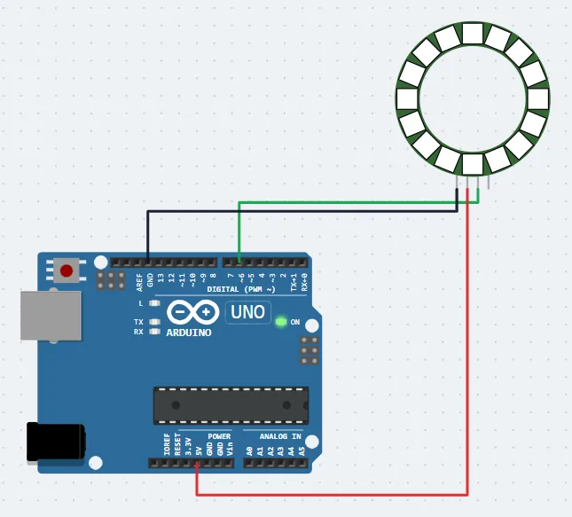
Lesson 22NeoPixel rainbow ring

Open in SkyNex Lab →
Circuit of the lesson “NeoPixel rainbow ring” in SkyNex Lab

You will learn: Addressable RGB LEDs: 16 colours on one wire.

Parts and wiring

  • ●Arduino Uno (USB to your computer)
  • ●NeoPixel ring (16 LEDs): Data in → pin 6, VCC → 5V, GND → GND

How the code works

  1. 1A NeoPixel ring has 16 RGB LEDs, each with its own little chip, all on one data pin (6).
  2. 2setPixelColor(i, colour) sets one LED; show() sends all the colours at once.
  3. 3ColorHSV(hue) picks a colour from the colour wheel; the hues are spread around the ring.
  4. 4Moving the starting hue a little each time makes the rainbow turn.
Show the code
// A rainbow turns around a ring of 16 NeoPixels (WS2812) on pin 6.
#include <Adafruit_NeoPixel.h>

const byte PIN = 6, COUNT = 16;
Adafruit_NeoPixel ring(COUNT, PIN, NEO_GRB + NEO_KHZ800);
uint16_t start = 0;

void setup() {
  ring.begin();
  ring.setBrightness(80);
}

void loop() {
  for (byte i = 0; i < COUNT; i++) {
    uint16_t hue = start + i * (65536L / COUNT);   // spread the colour wheel over the ring
    ring.setPixelColor(i, ring.gamma32(ring.ColorHSV(hue)));
  }
  ring.show();
  start += 1024;
  delay(30);
}

Try this

  • Make the rainbow turn the other way, or faster.
  • Light only one LED and make it run around the ring.

Part 5 · Sensors

Measuring the world: light, tilt, temperature, motion, distance, gas, flame, humidity, knobs, keys, frequency and angles.

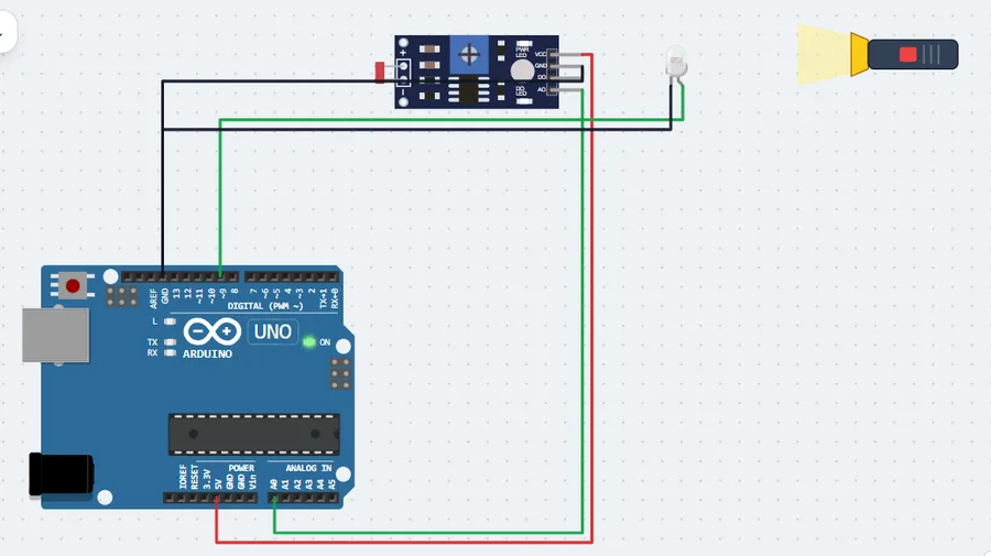
Lesson 23Light meter and night light

Open in SkyNex Lab →
Circuit of the lesson “Light meter and night light” in SkyNex Lab

You will learn: Measuring light with a photoresistor.

Parts and wiring

  • ●Arduino Uno (USB to your computer)
  • ●Light sensor (LDR): Analog out → A0, VCC → 5V, GND → GND
  • ●LED: Anode (+) → pin 9, GND → GND

How the code works

  1. 1The LDR module gives a low reading in bright light and a high reading in the dark.
  2. 2map() turns it into a percentage of light.
  3. 3The LED on pin 9 gets brighter when it gets darker: a night light.
  4. 4Test it with the torch: drag it next to the sensor and click it ON. The light level goes up and the night light dims; click it OFF (or take it away) and it gets dark again.
Show the code
// A photoresistor (LDR) changes its resistance with light. The module on A0 gives a
// LOW reading in bright light and a HIGH reading in the dark.
// Press Run, then drag the torch close to the sensor and click it ON / OFF: the darker it is,
// the brighter the LED (pin 9).

void setup() {
  Serial.begin(9600);
  pinMode(9, OUTPUT);
}

void loop() {
  int raw = analogRead(A0);          // 0 (bright) … 1023 (dark)
  int light = map(raw, 1023, 0, 0, 100);
  analogWrite(9, map(raw, 0, 1023, 0, 255));   // night light: dark = bright LED
  Serial.print("Light: ");
  Serial.print(light);
  Serial.println(" %");
  delay(300);
}

Try this

  • Switch the LED fully on below 20 % light.
  • Show the light level on the bar graph.

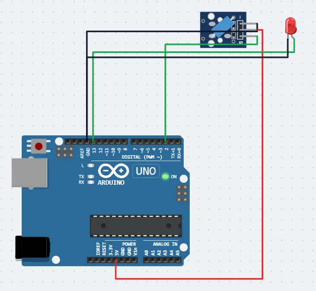
Lesson 24Tilt switch alarm

Open in SkyNex Lab →
Circuit of the lesson “Tilt switch alarm” in SkyNex Lab

You will learn: A simple digital sensor.

Parts and wiring

  • ●Arduino Uno (USB to your computer)
  • ●Tilt switch: OUT → pin 2, VCC → 5V, GND → GND
  • ●LED: Anode (+) → pin 13, GND → GND

How the code works

  1. 1A tilt switch closes (or opens) when it is tilted.
  2. 2digitalRead() tells if it is tilted (HIGH).
  3. 3The LED on pin 13 lights and the Serial Monitor prints Tilted! or Level.
Show the code
// A tilt switch tells you when something has been knocked over.
// In the simulator: click the tilt switch and tick "Tilted".
const int TILT = 2;
const int LED = 13;

void setup() {
  pinMode(TILT, INPUT);
  pinMode(LED, OUTPUT);
  Serial.begin(9600);
}

void loop() {
  bool tilted = digitalRead(TILT) == HIGH;
  digitalWrite(LED, tilted ? HIGH : LOW);
  Serial.println(tilted ? "Tilted!" : "Level");
  delay(250);
}

Try this

  • Add a buzzer that sounds when it is tilted.
  • Count how many times it was tilted.

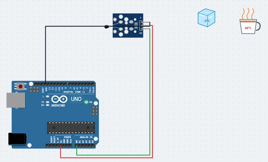
Lesson 25Digital thermometer

Open in SkyNex Lab →
Circuit of the lesson “Digital thermometer” in SkyNex Lab

You will learn: Turning a sensor’s resistance into degrees.

Parts and wiring

  • ●Arduino Uno (USB to your computer)
  • ●Temperature sensor (NTC): OUT → A0, VCC → 5V, GND → GND

How the code works

  1. 1An NTC thermistor’s resistance goes down when it gets warmer.
  2. 2With a resistor it forms a voltage divider read on A0.
  3. 3The beta formula turns the reading into °C, printed to the Serial Monitor.
  4. 4Test it with the ice cube (−5 °C) and the cup of hot water (80 °C): drag one next to the sensor while it runs and watch the temperature fall or rise, then move it away and it slowly returns to room temperature.
Show the code
// Read a 10k NTC thermistor (beta 3950) and print the temperature.
// In the simulator: press Run, then drag the ice cube or the cup of hot water next to the
// sensor and watch the temperature change (the slider in the sensor settings sets the room temperature).
const float BETA = 3950;

void setup() {
  Serial.begin(9600);
}

void loop() {
  int raw = analogRead(A0);
  // convert the reading to degrees Celsius with the beta formula
  float celsius = 1 / (log(1 / (1023.0 / raw - 1)) / BETA + 1.0 / 298.15) - 273.15;
  Serial.print("Temperature: ");
  Serial.print(celsius, 1);
  Serial.println(" C");
  delay(1000);
}

Try this

  • Light a blue LED below 10 °C and a red LED above 40 °C, then test with the ice and the hot cup.
  • Show the temperature on the LCD.

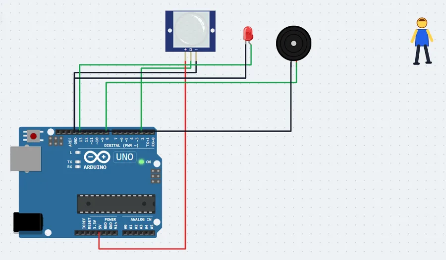
Lesson 26Motion alarm with a PIR sensor

Open in SkyNex Lab →
Circuit of the lesson “Motion alarm with a PIR sensor” in SkyNex Lab

You will learn: Detecting people with infrared.

Parts and wiring

  • ●Arduino Uno (USB to your computer)
  • ●PIR motion sensor: OUT → pin 2, VCC → 5V, GND → GND
  • ●LED: Anode (+) → pin 13, GND → GND
  • ●Buzzer: Signal → pin 8, GND → GND

How the code works

  1. 1A PIR sensor sees the heat of a moving body; its OUT pin goes HIGH.
  2. 2While digitalRead() on that pin is HIGH, the LED flashes and the buzzer beeps.
  3. 3The Serial Monitor prints Motion detected! each time.
  4. 4Test it with the little person: press Run, then drag the person in front of the sensor. Moving within its range sets off the alarm; when the person stands still or leaves, it stops after about 3 seconds.
Show the code
// When the PIR sensor sees motion, flash the LED and sound the buzzer.
// In the simulator: press Run, then drag the little person in front of the PIR sensor
// (or click the PIR and press "Trigger motion").
const int PIR = 2;
const int LED = 13;
const int BUZZER = 8;

void setup() {
  pinMode(PIR, INPUT);
  pinMode(LED, OUTPUT);
  Serial.begin(9600);
  Serial.println("Alarm armed");
}

void loop() {
  if (digitalRead(PIR) == HIGH) {
    Serial.println("Motion detected!");
    digitalWrite(LED, HIGH);
    tone(BUZZER, 1500, 150);
    delay(300);
    digitalWrite(LED, LOW);
    delay(200);
  }
}

Try this

  • Count the people that pass.
  • Switch on a lamp through the relay when someone comes in.

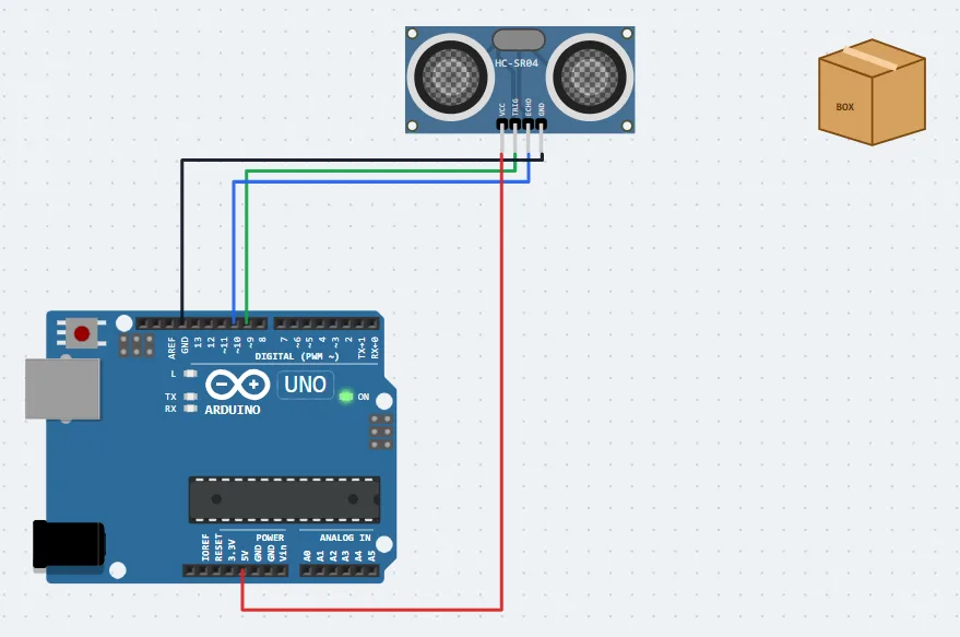
Lesson 27Distance with an ultrasonic sensor

Open in SkyNex Lab →
Circuit of the lesson “Distance with an ultrasonic sensor” in SkyNex Lab

You will learn: Measuring distance with sound echoes.

Parts and wiring

  • ●Arduino Uno (USB to your computer)
  • ●HC-SR04 ultrasonic: TRIG → pin 9, ECHO → pin 10, VCC → 5V, GND → GND

How the code works

  1. 1A 10 µs pulse on TRIG sends an ultrasonic burst.
  2. 2pulseIn(ECHO, HIGH) measures how long the echo takes to come back.
  3. 3distance (cm) = time (µs) × 0.0343 / 2: sound travels 343 m/s and goes there and back.
  4. 4Test it with the box: press Run and drag the box closer to or further from the sensor; the distance in the Serial Monitor follows.
Show the code
// measure distance with the HC-SR04 ultrasonic sensor
// Wiring: VCC 5V, GND GND, TRIG pin 9, ECHO pin 10
// In the simulator: press Run, then drag the box closer to or further from the sensor.

const int TRIG = 9;
const int ECHO = 10;

void setup() {
  Serial.begin(9600);
  pinMode(TRIG, OUTPUT);
  pinMode(ECHO, INPUT);
}

void loop() {
  digitalWrite(TRIG, LOW);
  delayMicroseconds(2);
  digitalWrite(TRIG, HIGH);
  delayMicroseconds(10);
  digitalWrite(TRIG, LOW);

  long duration = pulseIn(ECHO, HIGH, 30000); // time for the echo, in microseconds
  float cm = duration * 0.0343 / 2;           // speed of sound: 343 m/s

  Serial.print("Distance: ");
  Serial.print(cm);
  Serial.println(" cm");
  delay(300);
}

Try this

  • Beep faster as an object gets closer (parking sensor).
  • Light a red LED below 10 cm.

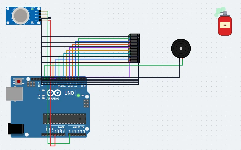
Lesson 28Gas alarm with a level meter

Open in SkyNex Lab →
Circuit of the lesson “Gas alarm with a level meter” in SkyNex Lab

You will learn: Reading an analog sensor and showing it on a bar graph.

Parts and wiring

  • ●Arduino Uno (USB to your computer)
  • ●Gas sensor (MQ-2): AOUT → A0, VCC → 5V, GND → GND
  • ●LED bar graph (10): LED 1 → pin 2, LED 2 → pin 3, LED 3 → pin 4, LED 4 → pin 5, LED 5 → pin 6, LED 6 → pin 7, LED 7 → pin 8, LED 8 → pin 9, LED 9 → pin 10, LED 10 → pin 11, GND → GND
  • ●Buzzer: Signal → pin 12, GND → GND

How the code works

  1. 1The MQ-2 gas sensor gives a higher voltage on A0 when there is more gas.
  2. 2map() and constrain() turn the reading into 0–100 %.
  3. 3Each 10 % lights one more LED of the bar graph (pins 2–11), and above 60 % the buzzer beeps.
  4. 4Test it: press Run and drag the gas bottle next to the sensor; move it away and the gas clears.
Show the code
// MQ-2 gas sensor: show the gas level on an LED bar graph and beep above 60%.
// In the simulator: press Run, then drag the gas bottle next to the sensor and watch the bar
// graph rise and the buzzer start above 60%. Move it away and the gas clears.
const int GAS = A0;
const int BUZZER = 12;
const int FIRST_LED = 2;   // bar graph on pins 2..11

void setup() {
  for (int i = 0; i < 10; i++) pinMode(FIRST_LED + i, OUTPUT);
  Serial.begin(9600);
}

void loop() {
  int value = analogRead(GAS);
  int percent = map(value, 80, 940, 0, 100);
  percent = constrain(percent, 0, 100);
  int lit = percent / 10;
  for (int i = 0; i < 10; i++) digitalWrite(FIRST_LED + i, i < lit ? HIGH : LOW);

  Serial.print("Gas: "); Serial.print(percent); Serial.println("%");
  if (percent > 60) tone(BUZZER, 2000, 200);
  delay(300);
}

Try this

  • Make the beeps faster as the gas level rises.
  • Switch on a fan through a relay above 60 %.

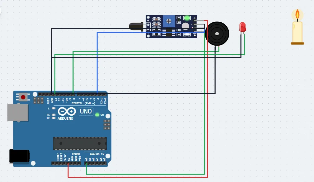
Lesson 29Flame alarm

Open in SkyNex Lab →
Circuit of the lesson “Flame alarm” in SkyNex Lab

You will learn: Using a sensor’s digital and analog outputs together.

Parts and wiring

  • ●Arduino Uno (USB to your computer)
  • ●Flame sensor: AOUT → A0, DOUT → pin 2, VCC → 5V, GND → GND
  • ●Buzzer: Signal → pin 8, GND → GND
  • ●LED: Anode (+) → pin 13, GND → GND

How the code works

  1. 1The flame sensor’s DOUT (pin 2) goes LOW when it sees a flame; AOUT (A0) gives the flame strength.
  2. 2When there is fire, the red LED on pin 13 lights and the buzzer on pin 8 sounds.
  3. 3The Serial Monitor prints the flame level.
  4. 4Test it: press Run and drag the candle next to the sensor.
Show the code
// When the flame sensor (DOUT on pin 2, AOUT on A0) sees fire, the buzzer (pin 8)
// and the red LED (pin 13) go off. Press Run, then drag the candle next to the sensor to test it.

void setup() {
  Serial.begin(9600);
  pinMode(2, INPUT);
  pinMode(13, OUTPUT);
}

void loop() {
  bool fire = digitalRead(2) == LOW;
  digitalWrite(13, fire);
  if (fire) tone(8, 1500); else noTone(8);
  Serial.print("Flame level: ");
  Serial.println(1023 - analogRead(A0));
  delay(200);
}

Try this

  • Flash the LED instead of keeping it on.
  • Sound the alarm only if the flame lasts more than 2 seconds.

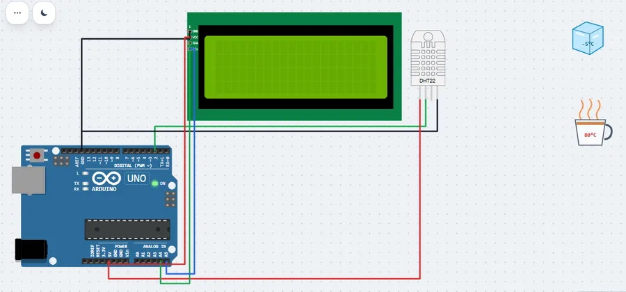
Lesson 30Temperature and humidity (DHT sensor)

Open in SkyNex Lab →
Circuit of the lesson “Temperature and humidity (DHT sensor)” in SkyNex Lab

You will learn: Using a digital sensor with its library.

Parts and wiring

  • ●Arduino Uno (USB to your computer)
  • ●DHT22 temperature + humidity: Data → pin 2, VCC → 5V, GND → GND
  • ●LCD 20x4 (I2C): SDA → A4, SCL → A5, VCC → 5V, GND → GND

How the code works

  1. 1The DHT sensor sends temperature and humidity over one data wire.
  2. 2dht.readTemperature() and dht.readHumidity() return the values.
  3. 3They are shown on the LCD and refreshed every 2 seconds.
  4. 4Test it with the ice cube and the hot cup: drag one next to the DHT22 and watch the LCD. The hot cup makes it warmer and its steam raises the humidity (toward 90 %); the ice makes it colder, and the cooler air raises the relative humidity a little (toward 70 %).
Show the code
// Temperature and humidity from a DHT22 (data on pin 2) on a 20x4 I2C LCD.
// Press Run, then drag the ice cube or the hot cup next to the DHT22: the temperature and the
// humidity change (the hot cup's steam makes the air humid).
#include <DHT.h>
#include <LiquidCrystal_I2C.h>

DHT dht(2, DHT22);
LiquidCrystal_I2C lcd(0x27, 20, 4);

void setup() {
  dht.begin();
  lcd.init();
  lcd.backlight();
  lcd.setCursor(0, 0);
  lcd.print("SkyNex weather");
}

void loop() {
  float t = dht.readTemperature();
  float h = dht.readHumidity();
  lcd.setCursor(0, 1);
  if (isnan(t) || isnan(h)) {
    lcd.print("Sensor error        ");
  } else {
    lcd.print("Temp:     "); lcd.print(t, 1); lcd.print(" C   ");
    lcd.setCursor(0, 2);
    lcd.print("Humidity: "); lcd.print(h, 1); lcd.print(" %   ");
    lcd.setCursor(0, 3);
    lcd.print(t > 30 ? "It is hot!          " : t < 10 ? "It is cold!         " : h > 70 ? "Very humid          " : "Comfortable         ");
  }
  delay(2000);                     // the DHT22 needs 2 seconds between readings
}

Try this

  • Add a warning when the air is too dry (below 30 %).
  • Show °F as well.

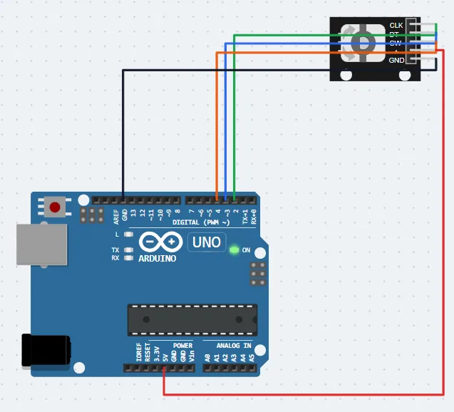
Lesson 31Rotary encoder counter

Open in SkyNex Lab →
Circuit of the lesson “Rotary encoder counter” in SkyNex Lab

You will learn: Reading a knob that turns forever, in both directions.

Parts and wiring

  • ●Arduino Uno (USB to your computer)
  • ●Rotary encoder (KY-040): CLK → pin 2, DT → pin 3, Button → pin 4, VCC → 5V, GND → GND

How the code works

  1. 1The KY-040 encoder gives two signals, CLK (pin 2) and DT (pin 3), that switch one after the other.
  2. 2When CLK falls, DT gives the direction: HIGH = clockwise (+1), LOW = anticlockwise (−1).
  3. 3Pressing the knob (SW, pin 4) resets the count to 0.
  4. 4Test it: press Run, turn the knob both ways, then press it.
Show the code
// Turn the KY-040 knob to count up and down; press it to reset.
// CLK on 2, DT on 3, SW on 4. Watch the Serial Monitor.

const byte CLK = 2, DT = 3, SW = 4;
int count = 0;
int lastClk;

void setup() {
  Serial.begin(9600);
  pinMode(CLK, INPUT_PULLUP);
  pinMode(DT, INPUT_PULLUP);
  pinMode(SW, INPUT_PULLUP);
  lastClk = digitalRead(CLK);
}

void loop() {
  int clk = digitalRead(CLK);
  if (clk != lastClk && clk == LOW) {          // CLK just fell: one click
    count += digitalRead(DT) == HIGH ? 1 : -1;   // DT still HIGH = clockwise
    Serial.print("Count: ");
    Serial.println(count);
  }
  lastClk = clk;
  if (digitalRead(SW) == LOW && count != 0) {
    count = 0;
    Serial.println("Reset");
  }
}

Try this

  • Limit the count to 0–100, like a volume knob.
  • Use the count to set an LED’s brightness.

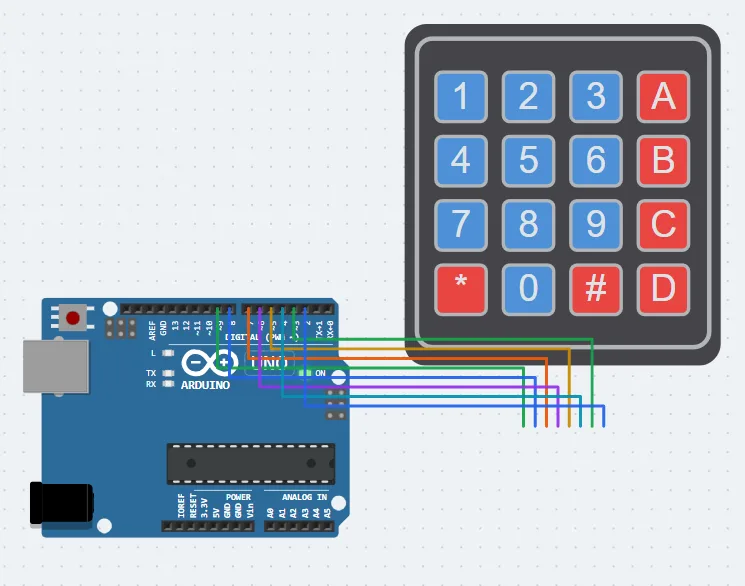
Lesson 32Read a 4x4 keypad

Open in SkyNex Lab →
Circuit of the lesson “Read a 4x4 keypad” in SkyNex Lab

You will learn: Scanning a matrix of keys.

Parts and wiring

  • ●Arduino Uno (USB to your computer)
  • ●Keypad 4x4: Row 1 → pin 9, Row 2 → pin 8, Row 3 → pin 7, Row 4 → pin 6, Column 1 → pin 5, Column 2 → pin 4, Column 3 → pin 3, Column 4 → pin 2

How the code works

  1. 116 keys use only 8 wires: 4 rows and 4 columns.
  2. 2One row at a time is made LOW; a pressed key pulls its column LOW.
  3. 3The row and column numbers give the key from a table.
Show the code
// 16 keys on 8 wires: rows on pins 9, 8, 7, 6 and columns on 5, 4, 3, 2.
// Scan: make one row LOW at a time and look which column goes LOW.
// Click the keys (or type on your keyboard) and watch the Serial Monitor.

const byte ROWS[4] = { 9, 8, 7, 6 };
const byte COLS[4] = { 5, 4, 3, 2 };
const char KEYS[4][4] = {
  { '1', '2', '3', 'A' },
  { '4', '5', '6', 'B' },
  { '7', '8', '9', 'C' },
  { '*', '0', '#', 'D' },
};
char last = 0;

char scan() {
  for (int r = 0; r < 4; r++) {
    digitalWrite(ROWS[r], LOW);
    for (int c = 0; c < 4; c++) {
      if (digitalRead(COLS[c]) == LOW) {
        digitalWrite(ROWS[r], HIGH);
        return KEYS[r][c];
      }
    }
    digitalWrite(ROWS[r], HIGH);
  }
  return 0;   // no key pressed
}

void setup() {
  Serial.begin(9600);
  for (int i = 0; i < 4; i++) {
    pinMode(ROWS[i], OUTPUT);
    digitalWrite(ROWS[i], HIGH);
    pinMode(COLS[i], INPUT_PULLUP);
  }
  Serial.println("Press a key...");
}

void loop() {
  char k = scan();
  if (k && k != last) {
    Serial.print("Key: ");
    Serial.println(k);
  }
  last = k;
  delay(30);
}

Try this

  • Make a 4-digit code lock with an LED.
  • Show the key on the LCD.

Lesson 33Frequency meter with an NE555

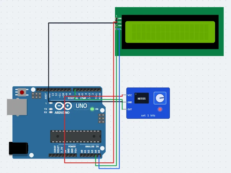
Open in SkyNex Lab →
Circuit of the lesson “Frequency meter with an NE555” in SkyNex Lab

You will learn: Measuring a signal’s period and frequency with pulseIn.

Parts and wiring

  • ●Arduino Uno (USB to your computer)
  • ●NE555 square-wave generator: OUT → pin 7, VCC → 5V, GND → GND
  • ●LCD 16x2 (I2C): SDA → A4, SCL → A5, VCC → 5V, GND → GND

How the code works

  1. 1The NE555 timer module makes a square wave: HIGH, LOW, HIGH, LOW… Its potentiometer sets how fast.
  2. 2pulseIn(pin, HIGH) returns how many microseconds the signal stays HIGH; pulseIn(pin, LOW) how long it stays LOW.
  3. 3One period T = HIGH + LOW time, and the frequency f = 1 / T, so f = 1 000 000 / T when T is in µs.
  4. 4The LCD shows f in Hz and T in µs, and the Serial Monitor prints them too.
  5. 5Test it: select the NE555 and move its Frequency slider (its potentiometer), even while the code runs; the meter follows.
Show the code
// Frequency meter: an NE555 module makes a square wave on pin 7.
// pulseIn measures how long the signal stays HIGH and LOW (in microseconds);
// one period T = HIGH + LOW, and the frequency f = 1 / T.
// Turn the 555's potentiometer (part settings) and watch the LCD follow.

#include <Wire.h>
#include <LiquidCrystal_I2C.h>

LiquidCrystal_I2C lcd(0x27, 16, 2);
const byte SIGNAL_PIN = 7;

void setup() {
  pinMode(SIGNAL_PIN, INPUT);
  Serial.begin(9600);
  lcd.init();
  lcd.backlight();
  lcd.print("Frequency meter");
  delay(800);
}

void loop() {
  unsigned long high = pulseIn(SIGNAL_PIN, HIGH, 1000000UL);   // wait at most 1 s
  unsigned long low  = pulseIn(SIGNAL_PIN, LOW, 1000000UL);
  lcd.clear();
  if (high == 0 || low == 0) {
    lcd.print("No signal");
    Serial.println("No signal");
  } else {
    unsigned long period = high + low;           // microseconds
    float f = 1000000.0 / period;
    lcd.print("f = ");
    lcd.print(f, 1);
    lcd.print(" Hz");
    lcd.setCursor(0, 1);
    lcd.print("T = ");
    lcd.print(period);
    lcd.print(" us");
    Serial.print("Frequency: ");
    Serial.print(f, 1);
    Serial.print(" Hz   period: ");
    Serial.print(period);
    Serial.println(" us");
  }
  delay(400);
}

Try this

  • Show the duty cycle too: HIGH time × 100 / period.
  • Show kHz when the frequency is above 1000 Hz.

Lesson 34Tilt angles with an MPU6050

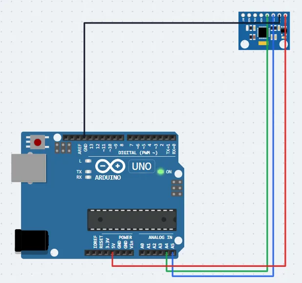
Open in SkyNex Lab →
Circuit of the lesson “Tilt angles with an MPU6050” in SkyNex Lab

You will learn: Reading an accelerometer over I2C.

Parts and wiring

  • ●Arduino Uno (USB to your computer)
  • ●MPU6050 accelerometer + gyro: SDA → A4, SCL → A5, VCC → 5V, GND → GND

How the code works

  1. 1The MPU6050 measures acceleration on 3 axes, including gravity.
  2. 2The program reads 6 bytes from its registers with the Wire library.
  3. 3atan2() turns the gravity direction into pitch and roll angles.
Show the code
// Reads the MPU6050 accelerometer with Wire and prints the tilt angles.
// Tilt the part in its settings while it runs. I2C address 0x68.
#include <Wire.h>

const byte MPU = 0x68;

int16_t read16() {
  return (Wire.read() << 8) | Wire.read();
}

void setup() {
  Serial.begin(9600);
  Wire.begin();
  Wire.beginTransmission(MPU);
  Wire.write(0x6B);     // power management register
  Wire.write(0);        // wake up
  Wire.endTransmission();
}

void loop() {
  Wire.beginTransmission(MPU);
  Wire.write(0x3B);     // first accelerometer register
  Wire.endTransmission();
  Wire.requestFrom(MPU, (byte)6);
  float ax = read16() / 16384.0, ay = read16() / 16384.0, az = read16() / 16384.0;  // in g
  float pitch = atan2(ax, sqrt(ay * ay + az * az)) * 180 / PI;
  float roll = atan2(ay, sqrt(ax * ax + az * az)) * 180 / PI;
  Serial.print("Pitch: "); Serial.print(pitch, 0);
  Serial.print("   Roll: "); Serial.println(roll, 0);
  delay(300);
}

Try this

  • Light an LED when it is tilted more than 30°.
  • Move the servo with the tilt.

Part 6 · Motors and relays

Making things move and switching big loads: relays, servos, DC motors and stepper motors, up to a light-tracking robot.

Lesson 35Relay switches a lamp

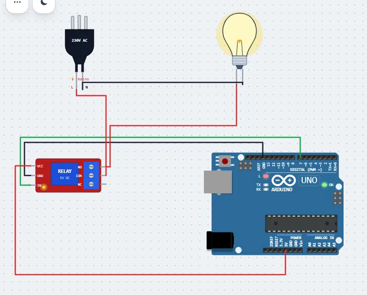
Open in SkyNex Lab →
Circuit of the lesson “Relay switches a lamp” in SkyNex Lab

You will learn: Using a relay so a small 5 V Arduino pin can safely switch a 230 V lamp.

Parts and wiring

  • ●Arduino Uno (USB to your computer)
  • ●Relay module: IN → pin 7, VCC → 5V, GND → GND
  • ●230 V side (through the relay): AC mains plug L → Relay module COM, Relay module NO → Light bulb 1, Light bulb 2 → AC mains plug N

How the code works

  1. 1The relay has two separate sides. Low-power side: Arduino 5V to VCC, GND to GND, pin 7 to IN.
  2. 2High-power side: the AC plug’s live wire L goes to COM, NO goes to the lamp, and the lamp goes back to neutral N.
  3. 3digitalWrite(7, HIGH) energises the coil (you hear a click): COM connects to NO, the circuit closes and the lamp lights.
  4. 4digitalWrite(7, LOW) releases it: COM goes back to NC, the circuit opens and the lamp goes out. The loop repeats every 2 seconds.
Show the code
// A relay is a switch moved by a small electromagnet. A tiny current from pin 7 (5 V side)
// switches a big load on the 230 V side: here a lamp powered by the AC mains plug.
// Low-power side:  Arduino 5V -> VCC, GND -> GND, pin 7 -> IN
// High-power side: plug L -> COM, NO -> lamp, lamp -> plug N
// Never wire mains voltage on a real board yourself: ask a qualified electrician.

const int RELAY = 7;

void setup() {
  pinMode(RELAY, OUTPUT);
  pinMode(LED_BUILTIN, OUTPUT);
  Serial.begin(9600);
}

void loop() {
  digitalWrite(RELAY, HIGH);       // relay on: COM connects to NO, the lamp circuit closes
  digitalWrite(LED_BUILTIN, HIGH);
  Serial.println("Relay ON  (click!) - lamp ON");
  delay(2000);
  digitalWrite(RELAY, LOW);        // relay off: COM goes back to NC, the lamp circuit opens
  digitalWrite(LED_BUILTIN, LOW);
  Serial.println("Relay OFF - lamp OFF");
  delay(2000);
}

Try this

  • Move the lamp wire from NO to NC: now the lamp is on when the relay is off.
  • Switch the lamp with a button instead of the timer.
  • Safety: never touch or wire 230 V yourself; the Lab is the safe place to practise.

Lesson 36Servo sweep

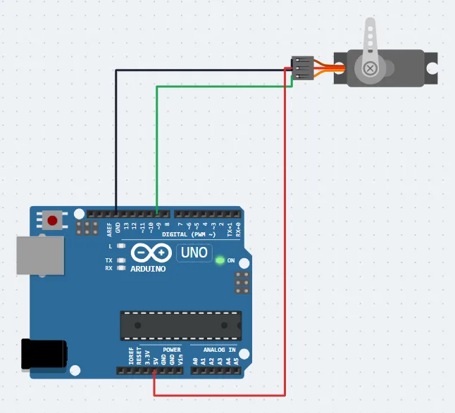
Open in SkyNex Lab →
Circuit of the lesson “Servo sweep” in SkyNex Lab

You will learn: Controlling a servo motor angle with the Servo library.

Parts and wiring

  • ●Arduino Uno (USB to your computer)
  • ●Servo motor: Signal → pin 9, VCC → 5V, GND → GND

How the code works

  1. 1#include <Servo.h>; myServo.attach(9) connects it to pin 9.
  2. 2myServo.write(angle) turns it to 0–180°.
  3. 3Two for loops sweep from 0 to 180 and back.
Show the code
// sweep an SG90 servo from 0 to 180 degrees (signal on pin 9)
#include <Servo.h>

Servo myServo;

void setup() {
  myServo.attach(9);
}

void loop() {
  for (int angle = 0; angle <= 180; angle++) {
    myServo.write(angle);
    delay(15);
  }
  for (int angle = 180; angle >= 0; angle--) {
    myServo.write(angle);
    delay(15);
  }
}

Try this

  • Sweep only from 45° to 135°.
  • Set the angle with the potentiometer.

Lesson 37Joystick controls a servo

Open in SkyNex Lab →
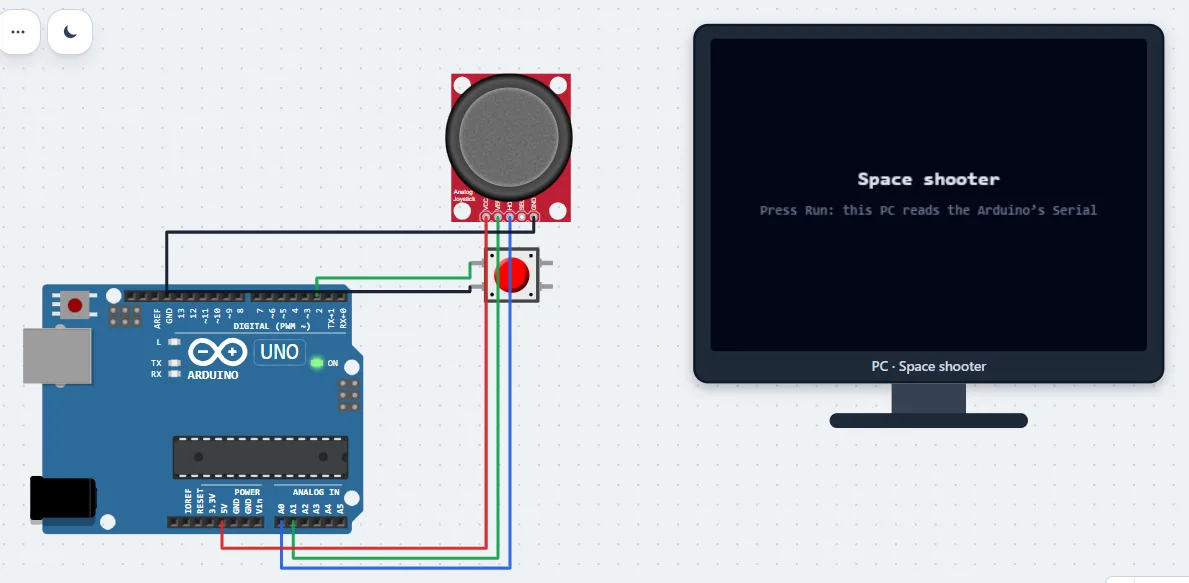
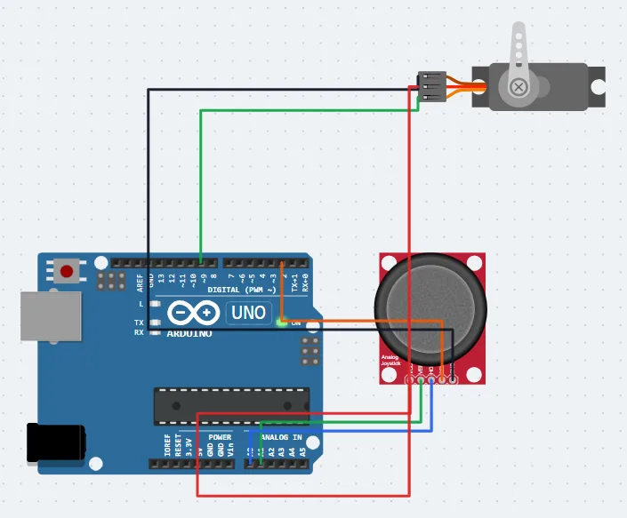
Circuit of the lesson “Joystick controls a servo” in SkyNex Lab

You will learn: Reading a two-axis joystick.

Parts and wiring

  • ●Arduino Uno (USB to your computer)
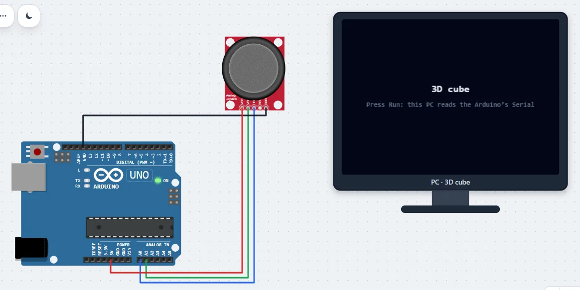
  • ●Analog joystick: Vertical → A1, Horizontal → A0, Button → pin 2, VCC → 5V, GND → GND
  • ●Servo motor: Signal → pin 9, VCC → 5V, GND → GND

How the code works

  1. 1The joystick has two potentiometers: X on one analog pin, Y on another, about 512 in the middle.
  2. 2map() turns the X reading into an angle for the servo.
  3. 3The joystick button reads LOW when pressed and centres the servo.
Show the code
// Push the joystick left and right to turn the servo (pin 9).
// HORZ on A0, VERT on A1, button on pin 2 (press it to centre the servo).
#include <Servo.h>

Servo servo;

void setup() {
  Serial.begin(9600);
  pinMode(2, INPUT_PULLUP);
  servo.attach(9);
}

void loop() {
  int x = analogRead(A0);            // about 512 in the middle
  int angle = map(x, 0, 1023, 180, 0);
  if (digitalRead(2) == LOW) angle = 90;
  servo.write(angle);
  Serial.print("x = "); Serial.print(x);
  Serial.print("  y = "); Serial.print(analogRead(A1));
  Serial.print("  angle = "); Serial.println(angle);
  delay(50);
}

Try this

  • Use the Y axis instead.
  • Make the servo move slowly toward the joystick position.

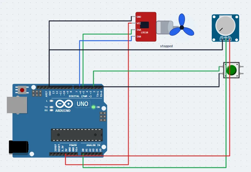
Lesson 38DC motor: speed and direction

Open in SkyNex Lab →
Circuit of the lesson “DC motor: speed and direction” in SkyNex Lab

You will learn: Driving a motor through a driver board, with PWM speed control.

Parts and wiring

  • ●Arduino Uno (USB to your computer)
  • ●DC motor with fan (L9110 driver): INA → pin 5, INB → pin 6, VCC → 5V, GND → GND
  • ●Potentiometer: Wiper → A0, VCC → 5V, GND → GND
  • ●Pushbutton: Signal → pin 2, GND → GND

How the code works

  1. 1An Arduino pin cannot power a motor: the L9110 driver board does it, the Arduino only tells it what to do.
  2. 2INA = PWM and INB = LOW turns the motor forward; INA = LOW and INB = PWM turns it backward; both LOW stops it.
  3. 3analogRead(A0) / 4 turns the potentiometer into a speed from 0 to 255 for analogWrite.
  4. 4Each press of the button flips the direction; the program stops the motor for 300 ms first, as you should with a real motor.
  5. 5Test it: press Run, turn the potentiometer and the fan speeds up; press the button and it turns the other way.
Show the code
// A DC motor with a fan, on an L9110 driver board.
// The potentiometer (A0) sets the speed; the button (pin 2) changes the direction.
// INA = PWM and INB = LOW: forward. INA = LOW and INB = PWM: backward.

const byte INA = 5, INB = 6;     // PWM pins
const byte BUTTON = 2;

bool forward = true;
bool lastButton = HIGH;
unsigned long printed = 0;

void setup() {
  pinMode(INA, OUTPUT);
  pinMode(INB, OUTPUT);
  pinMode(BUTTON, INPUT_PULLUP);
  Serial.begin(9600);
}

void loop() {
  bool b = digitalRead(BUTTON);
  if (b == LOW && lastButton == HIGH) {   // just pressed
    forward = !forward;
    analogWrite(INA, 0);                  // stop first: never reverse a spinning motor at once
    analogWrite(INB, 0);
    delay(300);
  }
  lastButton = b;

  int speed = analogRead(A0) / 4;         // 0 to 1023  ->  0 to 255
  if (forward) {
    analogWrite(INA, speed);
    analogWrite(INB, 0);
  } else {
    analogWrite(INA, 0);
    analogWrite(INB, speed);
  }

  if (millis() - printed > 500) {
    printed = millis();
    Serial.print(forward ? "Forward " : "Backward ");
    Serial.print(speed * 100 / 255);
    Serial.println(" %");
  }
  delay(20);
}

Try this

  • Make the motor start slowly and speed up (a soft start).
  • Show the speed on the LCD.

Lesson 39Stepper motor

Open in SkyNex Lab →
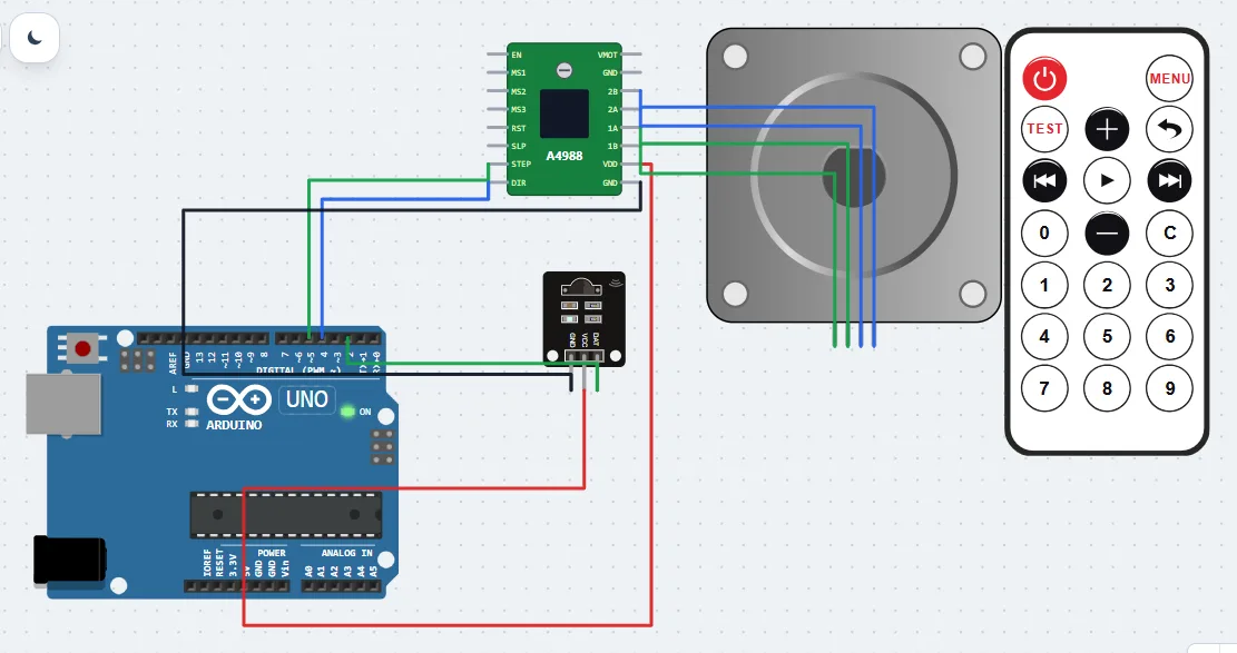
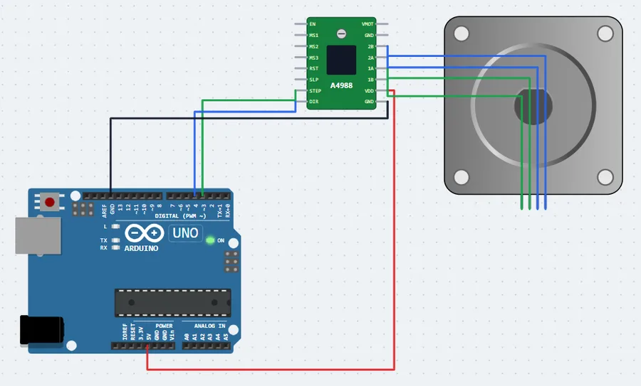
Circuit of the lesson “Stepper motor” in SkyNex Lab

You will learn: Precise turning, one step at a time, with a driver.

Parts and wiring

  • ●Arduino Uno (USB to your computer)
  • ●A4988 stepper driver: STEP → pin 3, DIR → pin 4, VCC → 5V, GND → GND
  • ●Between the parts: A4988 stepper driver 1A → Stepper motor A+, A4988 stepper driver 1B → Stepper motor A-, A4988 stepper driver 2A → Stepper motor B+, A4988 stepper driver 2B → Stepper motor B-

How the code works

  1. 1The A4988 driver needs only two pins: STEP (one pulse = one step) and DIR (direction).
  2. 2200 steps make one full turn of a standard stepper motor.
  3. 3The program turns one way, waits, then turns back.
Show the code
// Turn a stepper motor one full turn each way with an A4988 driver.
// STEP on pin 3, DIR on pin 4. 200 steps = one turn (1.8 degrees per step).

const byte STEP = 3, DIR = 4;

void turn(bool clockwise, int steps) {
  digitalWrite(DIR, clockwise ? HIGH : LOW);
  for (int i = 0; i < steps; i++) {
    digitalWrite(STEP, HIGH);
    delayMicroseconds(800);
    digitalWrite(STEP, LOW);
    delayMicroseconds(800);
  }
}

void setup() {
  pinMode(STEP, OUTPUT);
  pinMode(DIR, OUTPUT);
}

void loop() {
  turn(true, 200);
  delay(500);
  turn(false, 200);
  delay(500);
}

Try this

  • Turn exactly half a turn.
  • Make it turn faster (shorter pulses).

Lesson 40Light tracker (two LDRs + 360° servo)

Open in SkyNex Lab →
Circuit of the lesson “Light tracker (two LDRs + 360° servo)” in SkyNex Lab

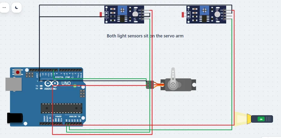
You will learn: A small control system: measure, compare, move, until the error is zero.

Parts and wiring

  • ●Arduino Uno (USB to your computer)
  • ●Light sensor (LDR): Analog out → A0, VCC → 5V, GND → GND
  • ●Light sensor (LDR): Analog out → A1, VCC → 5V, GND → GND
  • ●Servo motor: Signal → pin 9, VCC → 5V, GND → GND

How the code works

  1. 1Two light sensors are mounted on the arm of a 360° servo, one looking a little to each side.
  2. 2If one sensor sees more light, the light is on its side, so the servo turns 2° that way.
  3. 3When both see the same light, the arm points straight at the light and stops. Move the torch and it follows, all the way round.
  4. 4A 360° servo is driven with pulse widths: 500 µs = 0°, 2500 µs = 360° (writeMicroseconds).
  5. 5Test it with the torch: drag it anywhere around the servo and click it ON; the arm turns to face it. Click it OFF and the arm stops.
Show the code
// Light tracker: two light sensors (A0 and A1) sit on the arm of a 360° servo (pin 9),
// one looking a little to each side. The servo turns toward the brighter sensor until both
// see the same light: then the arm points straight at the light, like a sunflower.
// Press Run, then drag the torch anywhere around the servo (click it to switch it ON / OFF).

#include <Servo.h>

Servo turret;
float angle = 90;   // 0 to 360 degrees

int pulse(float a) {             // 360° servo: 500 µs = 0°, 2500 µs = 360°
  return 500 + a * 2000 / 360;
}

void setup() {
  Serial.begin(9600);
  turret.attach(9, 500, 2500);
  turret.writeMicroseconds(pulse(angle));
}

void loop() {
  int a = 1023 - analogRead(A0);   // bigger = more light
  int b = 1023 - analogRead(A1);
  int diff = a - b;
  if (diff > 20) angle += 2;          // sensor A sees more: turn its way
  else if (diff < -20) angle -= 2;    // sensor B sees more: turn the other way
  if (angle >= 360) angle -= 360;     // 360° is the same direction as 0°: keep turning round
  if (angle < 0) angle += 360;
  turret.writeMicroseconds(pulse(angle));
  Serial.print("A "); Serial.print(a);
  Serial.print("  B "); Serial.print(b);
  Serial.print("  Angle "); Serial.println(angle, 0);
  delay(30);
}

Try this

  • Make it react faster (bigger steps) or calmer (bigger dead band than 20).
  • Print the angle of the light to the Serial Monitor.

Part 7 · Remote control (infrared)

A TV remote sends invisible infrared light. With an IR receiver the Arduino reads its keys and can switch a lamp, choose colours or turn a motor.

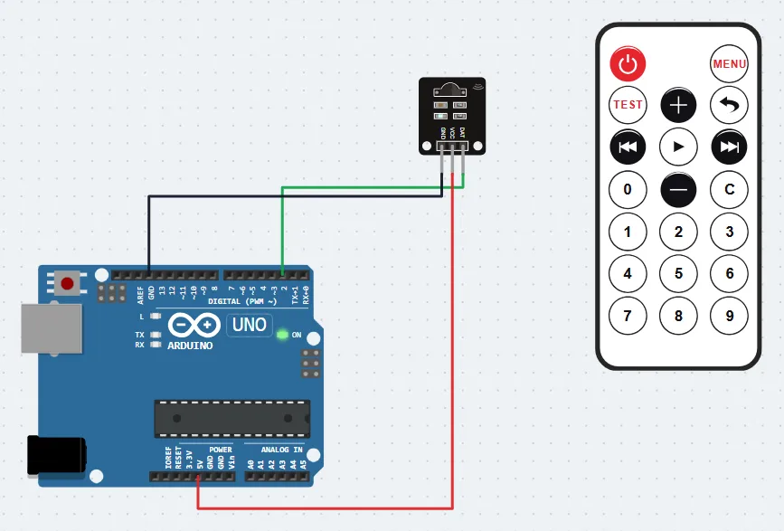
Lesson 41Read an IR remote control

Open in SkyNex Lab →
Circuit of the lesson “Read an IR remote control” in SkyNex Lab

You will learn: How an infrared remote sends codes, and how to read them.

Parts and wiring

  • ●Arduino Uno (USB to your computer)
  • ●IR receiver (38 kHz): DAT → pin 2, VCC → 5V, GND → GND

How the code works

  1. 1Each key of the remote flashes an infrared LED in a pattern (the NEC code): a start pulse, then 32 bits.
  2. 2The IR receiver turns the flashes into a digital signal on its DAT pin; the IRremote library decodes it.
  3. 3IrReceiver.decode() is true when a key arrived; decodedIRData.command is the key’s code (POWER = 0xA2, 1 = 0x30 …).
  4. 4Holding a key sends “repeat” frames; the program ignores them, prints the key name and code, then calls resume().
  5. 5Test it: press Run, then click the keys of the remote; the Serial Monitor shows each key.
Show the code
// Press Run, then click the keys of the remote control.
// Each key sends an infrared NEC code; the IR receiver on pin 2 picks it up
// and the IRremote library decodes it into a command number.

#include <IRremote.hpp>

const byte IR_PIN = 2;

const char* keyName(byte code) {
  switch (code) {
    case 0xA2: return "POWER";
    case 0xE2: return "MENU";
    case 0x22: return "TEST";
    case 0x02: return "+";
    case 0xC2: return "BACK";
    case 0xE0: return "PREV";
    case 0xA8: return "PLAY";
    case 0x90: return "NEXT";
    case 0x98: return "-";
    case 0xB0: return "C";
    case 0x68: return "0";
    case 0x30: return "1";
    case 0x18: return "2";
    case 0x7A: return "3";
    case 0x10: return "4";
    case 0x38: return "5";
    case 0x5A: return "6";
    case 0x42: return "7";
    case 0x4A: return "8";
    case 0x52: return "9";
    default:   return "?";
  }
}

void setup() {
  Serial.begin(9600);
  IrReceiver.begin(IR_PIN);
  Serial.println("Press a key on the remote");
}

void loop() {
  if (IrReceiver.decode()) {
    // holding a key sends "repeat" frames: ignore them
    if (!(IrReceiver.decodedIRData.flags & IRDATA_FLAGS_IS_REPEAT)) {
      byte code = IrReceiver.decodedIRData.command;
      Serial.print("Key ");
      Serial.print(keyName(code));
      Serial.print("   code 0x");
      Serial.println(code, HEX);
    }
    IrReceiver.resume();    // ready for the next key
  }
}

Try this

  • Write down the codes of all the keys.
  • Light the LED on pin 13 while you press POWER.

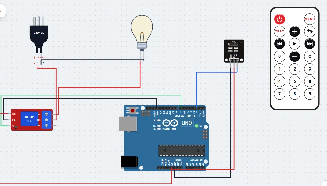
Lesson 42IR remote switches a lamp

Open in SkyNex Lab →
Circuit of the lesson “IR remote switches a lamp” in SkyNex Lab

You will learn: Combining the IR receiver with a relay: a remote-controlled 230 V lamp.

Parts and wiring

  • ●Arduino Uno (USB to your computer)
  • ●Relay module: IN → pin 7, VCC → 5V, GND → GND
  • ●IR receiver (38 kHz): DAT → pin 2, VCC → 5V, GND → GND
  • ●230 V side (through the relay): AC mains plug L → Relay module COM, Relay module NO → Light bulb 1, Light bulb 2 → AC mains plug N

How the code works

  1. 1The remote and the IR receiver work as in the previous lesson; readKey() returns a new key’s code, or 0.
  2. 2POWER toggles the lamp, 1 switches it ON, 0 switches it OFF.
  3. 3The Arduino drives the relay on pin 7; the relay contact (COM–NO) closes the 230 V circuit of the lamp.
  4. 4Test it: press Run, then click POWER, 1 and 0 on the remote and watch the lamp.
Show the code
// Switch a 230 V lamp from your sofa: the remote control talks to the IR receiver (pin 2),
// the Arduino drives the relay (pin 7) and the relay contact switches the lamp.
// POWER = toggle, 1 = ON, 0 = OFF.

#include <IRremote.hpp>

const byte IR_PIN = 2, RELAY = 7;
bool lampOn = false;

/** returns the code of a newly pressed key, or 0 when nothing new arrived */
byte readKey() {
  if (!IrReceiver.decode()) return 0;
  byte code = 0;
  if (!(IrReceiver.decodedIRData.flags & IRDATA_FLAGS_IS_REPEAT)) code = IrReceiver.decodedIRData.command;
  IrReceiver.resume();      // ready for the next key
  return code;
}

void setup() {
  pinMode(RELAY, OUTPUT);
  Serial.begin(9600);
  IrReceiver.begin(IR_PIN);
  Serial.println("POWER = toggle, 1 = on, 0 = off");
}

void loop() {
  byte key = readKey();
  if (key == 0) return;
  if (key == 0xA2) lampOn = !lampOn;      // POWER
  else if (key == 0x30) lampOn = true;    // 1
  else if (key == 0x68) lampOn = false;   // 0
  else return;
  digitalWrite(RELAY, lampOn ? HIGH : LOW);
  Serial.println(lampOn ? "Lamp ON" : "Lamp OFF");
}

Try this

  • Use the + key to switch the lamp off after 10 seconds (a sleep timer).
  • Control two relays with keys 1 and 2.

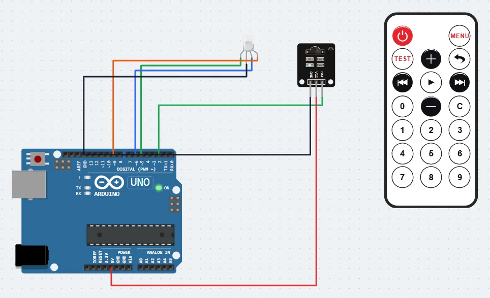
Lesson 43IR remote colours an RGB LED

Open in SkyNex Lab →
Circuit of the lesson “IR remote colours an RGB LED” in SkyNex Lab

You will learn: Choosing colours and brightness with remote keys.

Parts and wiring

  • ●Arduino Uno (USB to your computer)
  • ●RGB LED: Red → pin 5, Green → pin 6, Blue → pin 9, GND → GND
  • ●IR receiver (38 kHz): DAT → pin 2, VCC → 5V, GND → GND

How the code works

  1. 1The keys 1 to 7 choose a colour as red, green and blue amounts (0 to 255); 0 switches the LED off.
  2. 2+ and − change the brightness in steps of 20 %; every colour value is scaled by it.
  3. 3The LED uses pins 5, 6 and 9: the IRremote library uses timer 2, so pins 3 and 11 cannot make PWM here.
  4. 4Test it: press Run and click 1 to 7, then + and −.
Show the code
// Choose the colour of an RGB LED with the remote control.
// 1 red, 2 green, 3 blue, 4 yellow, 5 cyan, 6 magenta, 7 white, 0 off, + / - brightness.
// The LED uses pins 5, 6 and 9: IRremote needs timer 2, so pins 3 and 11 cannot do PWM here.

#include <IRremote.hpp>

const byte IR_PIN = 2, RED = 5, GREEN = 6, BLUE = 9;
byte r = 0, g = 0, b = 0;
int level = 100;          // brightness, percent

/** returns the code of a newly pressed key, or 0 when nothing new arrived */
byte readKey() {
  if (!IrReceiver.decode()) return 0;
  byte code = 0;
  if (!(IrReceiver.decodedIRData.flags & IRDATA_FLAGS_IS_REPEAT)) code = IrReceiver.decodedIRData.command;
  IrReceiver.resume();      // ready for the next key
  return code;
}

void show() {
  analogWrite(RED,   r * level / 100);
  analogWrite(GREEN, g * level / 100);
  analogWrite(BLUE,  b * level / 100);
  Serial.print("R "); Serial.print(r);
  Serial.print("  G "); Serial.print(g);
  Serial.print("  B "); Serial.print(b);
  Serial.print("  brightness "); Serial.print(level); Serial.println(" %");
}

void colour(byte red, byte green, byte blue) {
  r = red; g = green; b = blue;
}

void setup() {
  pinMode(RED, OUTPUT);
  pinMode(GREEN, OUTPUT);
  pinMode(BLUE, OUTPUT);
  Serial.begin(9600);
  IrReceiver.begin(IR_PIN);
  Serial.println("Press 1 to 7, 0, + or -");
}

void loop() {
  byte key = readKey();
  switch (key) {
    case 0x30: colour(255, 0, 0);     break;   // 1 red
    case 0x18: colour(0, 255, 0);     break;   // 2 green
    case 0x7A: colour(0, 0, 255);     break;   // 3 blue
    case 0x10: colour(255, 160, 0);   break;   // 4 yellow
    case 0x38: colour(0, 255, 255);   break;   // 5 cyan
    case 0x5A: colour(255, 0, 255);   break;   // 6 magenta
    case 0x42: colour(255, 255, 255); break;   // 7 white
    case 0x68: colour(0, 0, 0);       break;   // 0 off
    case 0x02: level = min(100, level + 20); break;   // +
    case 0x98: level = max(10, level - 20);  break;   // -
    default: return;                            // no key, or a key we do not use
  }
  show();
}

Try this

  • Make key 8 fade through all the colours.
  • Remember the last colour when you switch off and on with POWER.

Lesson 44IR remote turns a stepper motor

Open in SkyNex Lab →
Circuit of the lesson “IR remote turns a stepper motor” in SkyNex Lab

You will learn: Moving a stepper motor to exact positions from a remote.

Parts and wiring

  • ●Arduino Uno (USB to your computer)
  • ●A4988 stepper driver: STEP → pin 5, DIR → pin 4, VCC → 5V, GND → GND
  • ●IR receiver (38 kHz): DAT → pin 2, VCC → 5V, GND → GND
  • ●Between the parts: A4988 stepper driver 1A → Stepper motor A+, A4988 stepper driver 1B → Stepper motor A-, A4988 stepper driver 2A → Stepper motor B+, A4988 stepper driver 2B → Stepper motor B-

How the code works

  1. 1The A4988 driver moves the stepper one step (1.8°) for each pulse on STEP; DIR sets the direction.
  2. 2NEXT turns 25 steps (45°) clockwise, PREV 25 steps back, PLAY a full turn (200 steps).
  3. 3The program counts the steps in position, so 0 can send the motor back to where it started.
  4. 4Test it: press Run, then click NEXT, PREV, PLAY and 0 on the remote.
Show the code
// Turn a stepper motor with the remote control (A4988 driver: STEP pin 5, DIR pin 4).
// NEXT = 1/8 turn clockwise, PREV = 1/8 turn back, PLAY = one full turn, 0 = back to the start.
// The motor makes 200 steps per turn (1.8° per step).

#include <IRremote.hpp>

const byte IR_PIN = 2, STEP = 5, DIR = 4;
long position = 0;        // steps from the start

/** returns the code of a newly pressed key, or 0 when nothing new arrived */
byte readKey() {
  if (!IrReceiver.decode()) return 0;
  byte code = 0;
  if (!(IrReceiver.decodedIRData.flags & IRDATA_FLAGS_IS_REPEAT)) code = IrReceiver.decodedIRData.command;
  IrReceiver.resume();      // ready for the next key
  return code;
}

void move(long steps) {
  digitalWrite(DIR, steps > 0 ? HIGH : LOW);
  for (long i = 0; i < abs(steps); i++) {
    digitalWrite(STEP, HIGH);
    delayMicroseconds(800);
    digitalWrite(STEP, LOW);
    delayMicroseconds(800);
  }
  position += steps;
  Serial.print("Position: ");
  Serial.print(position * 1.8, 1);
  Serial.println(" degrees");
}

void setup() {
  pinMode(STEP, OUTPUT);
  pinMode(DIR, OUTPUT);
  Serial.begin(9600);
  IrReceiver.begin(IR_PIN);
  Serial.println("NEXT, PREV, PLAY or 0");
}

void loop() {
  byte key = readKey();
  if (key == 0x90) move(25);               // NEXT: 25 steps = 45°
  else if (key == 0xE0) move(-25);         // PREV
  else if (key == 0xA8) move(200);         // PLAY: a full turn
  else if (key == 0x68) move(-position);   // 0: home
}

Try this

  • Use keys 1 to 8 to go straight to 45°, 90° … 360°.
  • Make + and − change the speed.

Part 8 · Arduino and the computer

The Arduino talks to a program on the computer over USB: it draws and plays games with your sensors. In the Lab the PC screen runs that program for you; on real hardware, run the Processing sketch shown with each lesson.

Lesson 45Circle size from a potentiometer

Open in SkyNex Lab →
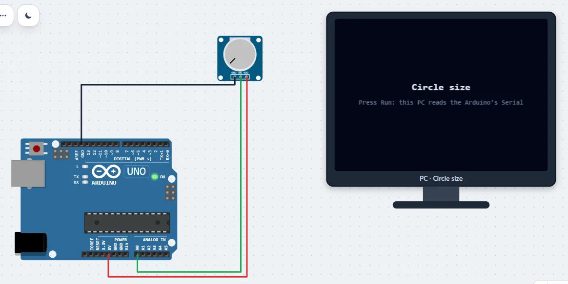
Circuit of the lesson “Circle size from a potentiometer” in SkyNex Lab

You will learn: Sending a value to the computer and drawing with it.

Parts and wiring

  • ●Arduino Uno (USB to your computer)
  • ●Potentiometer: Wiper → A0, VCC → 5V, GND → GND

How the code works

  1. 1The Arduino sends one number per line: analogRead(A0), 20 times a second.
  2. 2On the PC, the Processing program reads each line from the Serial port and turns it into a number.
  3. 3map() turns 0 … 1023 into a radius, and the circle is redrawn about 60 times a second.
  4. 4Test it: press Run and turn the potentiometer; the circle on the PC screen grows and shrinks.
Show the code
// The Arduino sends the potentiometer reading (0 to 1023) to the computer, one number per line.
// A program on the PC (Processing) reads the Serial port and draws a circle of that size.
// Press Run and turn the potentiometer: the circle on the PC screen grows and shrinks.

void setup() {
  Serial.begin(9600);
}

void loop() {
  Serial.println(analogRead(A0));
  delay(50);
}
Show the PC program (Processing)
// Processing sketch (runs on the computer): a circle sized by the Arduino's potentiometer
import processing.serial.*;

Serial port;
int value = 0;

void setup() {
  size(400, 400);
  port = new Serial(this, Serial.list()[0], 9600);   // the Arduino's USB port
  port.bufferUntil('\n');                            // call serialEvent() for each line
}

void serialEvent(Serial p) {
  String s = trim(p.readStringUntil('\n'));
  if (s != null && s.length() > 0) value = int(s);
}

void draw() {
  background(0);
  float r = map(value, 0, 1023, 5, 190);
  fill(0, 160, 255);
  noStroke();
  ellipse(width / 2, height / 2, r * 2, r * 2);
}

Try this

  • Change the colour with the value too.
  • Send two values (two potentiometers) for width and height of an ellipse.

Lesson 46Turn a 3D cube with a joystick

Open in SkyNex Lab →
Circuit of the lesson “Turn a 3D cube with a joystick” in SkyNex Lab

You will learn: Sending two values on one line and using them in 3D.

Parts and wiring

  • ●Arduino Uno (USB to your computer)
  • ●Analog joystick: Vertical → A1, Horizontal → A0, VCC → 5V, GND → GND

How the code works

  1. 1The joystick gives two analog values: HORZ on A0 and VERT on A1.
  2. 2The Arduino sends them as one line "x,y"; the PC splits the line at the comma.
  3. 3The further you push the joystick, the faster the cube turns; in the middle (about 512) it stops.
  4. 4Test it: press Run and drag the joystick knob.
Show the code
// The Arduino sends the joystick position to the computer as "x,y" (each 0 to 1023).
// The PC program turns a 3D cube: push the joystick and the cube turns that way,
// let it go back to the middle and the cube stops.

void setup() {
  Serial.begin(9600);
}

void loop() {
  int x = analogRead(A0);    // joystick HORZ
  int y = analogRead(A1);    // joystick VERT
  Serial.print(x);
  Serial.print(",");
  Serial.println(y);
  delay(40);
}
Show the PC program (Processing)
// Processing sketch (runs on the computer): a 3D cube turned by the Arduino's joystick
import processing.serial.*;

Serial port;
float x = 512, y = 512, rx = -0.5, ry = 0.6;

void setup() {
  size(400, 400, P3D);
  port = new Serial(this, Serial.list()[0], 9600);   // the Arduino's USB port
  port.bufferUntil('\n');                            // call serialEvent() for each line
}

void serialEvent(Serial p) {
  String[] v = split(trim(p.readStringUntil('\n')), ',');
  if (v.length == 2) {
    x = float(v[0]);
    y = float(v[1]);
  }
}

void draw() {
  background(0);
  float dx = (512 - x) / 512, dy = (y - 512) / 512;   // -1 … 1, 0 in the middle
  if (abs(dx) > 0.08) ry += dx * 0.06;
  if (abs(dy) > 0.08) rx += dy * 0.06;
  translate(width / 2, height / 2);
  rotateX(rx);
  rotateY(ry);
  noFill();
  stroke(0, 200, 255);
  strokeWeight(3);
  box(150);
}

Try this

  • Use the joystick button to reset the cube.
  • Draw a pyramid instead of a cube.

Lesson 47Snake game with two buttons

Open in SkyNex Lab →
Circuit of the lesson “Snake game with two buttons” in SkyNex Lab

You will learn: Using the Arduino as a game controller.

Parts and wiring

  • ●Arduino Uno (USB to your computer)
  • ●Pushbutton: Signal → pin 2, GND → GND
  • ●Pushbutton: Signal → pin 3, GND → GND

How the code works

  1. 1The left button (pin 2) sends “L” and the right button (pin 3) sends “R”, once per press.
  2. 2The game runs on the computer: the snake moves 5 squares a second and turns left or right on each letter.
  3. 3Eat the red food to grow; hitting a wall or your own tail ends the game, which restarts after a moment.
  4. 4Test it: press Run and click the two buttons to steer the snake.
Show the code
// Snake on the PC, played with two buttons on the Arduino.
// Left button (pin 2) sends "L", right button (pin 3) sends "R": the snake turns left or right.
// The game itself runs on the computer (Processing); the Arduino is the game controller.

const byte LEFT = 2, RIGHT = 3;
bool lastL = HIGH, lastR = HIGH;

void setup() {
  pinMode(LEFT, INPUT_PULLUP);
  pinMode(RIGHT, INPUT_PULLUP);
  Serial.begin(9600);
}

void loop() {
  bool l = digitalRead(LEFT), r = digitalRead(RIGHT);
  if (l == LOW && lastL == HIGH) Serial.println("L");   // send once per press
  if (r == LOW && lastR == HIGH) Serial.println("R");
  lastL = l;
  lastR = r;
  delay(10);   // debounce
}
Show the PC program (Processing)
// Processing sketch (runs on the computer): Snake, steered by "L" and "R" from the Arduino
import processing.serial.*;

Serial port;
int cols = 22, rows = 15, s = 20, dir = 0, score = 0, overAt = -1;
ArrayList<PVector> body = new ArrayList<PVector>();
PVector food;

void setup() {
  size(440, 300);
  frameRate(5);                 // 5 moves per second
  port = new Serial(this, Serial.list()[0], 9600);   // the Arduino's USB port
  port.bufferUntil('\n');                            // call serialEvent() for each line
  restart();
}

void restart() {
  body.clear();
  for (int i = 0; i < 3; i++) body.add(new PVector(8 - i, 9));
  dir = 0;
  score = 0;
  overAt = -1;
  food = new PVector(16, 9);
}

void serialEvent(Serial p) {
  String k = trim(p.readStringUntil('\n'));
  if (k.equals("L")) dir = (dir + 3) % 4;     // turn left
  if (k.equals("R")) dir = (dir + 1) % 4;     // turn right
}

void draw() {
  background(0);
  if (overAt < 0) {
    int[][] d = {{1, 0}, {0, 1}, {-1, 0}, {0, -1}};   // right, down, left, up
    PVector h = new PVector(body.get(0).x + d[dir][0], body.get(0).y + d[dir][1]);
    boolean crash = h.x < 0 || h.y < 0 || h.x >= cols || h.y >= rows;
    for (PVector b : body) if (b.x == h.x && b.y == h.y) crash = true;
    if (crash) overAt = frameCount;
    else {
    body.add(0, h);
    if (h.x == food.x && h.y == food.y) {
      score++;
      food = new PVector(int(random(cols)), int(random(rows)));
    } else body.remove(body.size() - 1);
    }
  } else if (frameCount - overAt > 12) restart();
  fill(255, 60, 60);
  rect(food.x * s, food.y * s, s, s);
  fill(60, 220, 90);
  for (PVector b : body) rect(b.x * s, b.y * s, s - 1, s - 1);
  fill(255);
  text("score " + score, 8, 16);
  if (overAt >= 0) {
    textSize(28);
    text("GAME OVER", 140, 150);
    textSize(12);
  }
}

Try this

  • Speed the snake up as the score grows.
  • Add a third button that pauses the game.

Lesson 48Space shooter game

Open in SkyNex Lab →
Circuit of the lesson “Space shooter game” in SkyNex Lab

You will learn: Sending a joystick and a button together for a real-time game.

Parts and wiring

  • ●Arduino Uno (USB to your computer)
  • ●Analog joystick: Vertical → A1, Horizontal → A0, VCC → 5V, GND → GND
  • ●Pushbutton: Signal → pin 2, GND → GND

How the code works

  1. 1The Arduino sends "x,y,fire" about 30 times a second: the joystick values and 1 while the button is pressed.
  2. 2On the PC, x moves the ship left and right, y moves it up and down (in the lower half); fire shoots (at most 4 shots a second).
  3. 3Flying saucers come down faster as your score grows; each one that lands or hits the ship costs a life, and you have 3.
  4. 4Test it: press Run, move the joystick and click the red button to fire.
Show the code
// A space shooter on the PC: the joystick moves the ship, the button (pin 2) fires.
// The Arduino sends "x,y,fire" about 30 times a second; the game runs on the computer.
// Shoot the flying saucers before they land: you have 3 lives.

const byte FIRE = 2;

void setup() {
  pinMode(FIRE, INPUT_PULLUP);
  Serial.begin(9600);
}

void loop() {
  Serial.print(analogRead(A0));        // joystick HORZ
  Serial.print(",");
  Serial.print(analogRead(A1));        // joystick VERT
  Serial.print(",");
  Serial.println(digitalRead(FIRE) == LOW ? 1 : 0);
  delay(30);
}
Show the PC program (Processing)
// Processing sketch (runs on the computer): a space shooter played with the Arduino's joystick and button
import processing.serial.*;

Serial port;
float x = 512, y = 512, shipX = 200, shipY = 273;
boolean fire = false;
ArrayList<PVector> shots = new ArrayList<PVector>(), saucers = new ArrayList<PVector>();
int score = 0, lives = 3, lastShot = 0;

void setup() {
  size(400, 300);
  port = new Serial(this, Serial.list()[0], 9600);   // the Arduino's USB port
  port.bufferUntil('\n');                            // call serialEvent() for each line
}

void serialEvent(Serial p) {
  String[] v = split(trim(p.readStringUntil('\n')), ',');
  if (v.length == 3) {
    x = float(v[0]);
    y = float(v[1]);
    fire = v[2].equals("1");
  }
}

void draw() {
  background(0);
  if (lives <= 0) {
    fill(255, 80, 80);
    textSize(28);
    text("GAME OVER", 120, 150);
    return;
  }
  float dx = (512 - x) / 512;
  if (abs(dx) > 0.08) shipX = constrain(shipX + dx * 5, 15, width - 15);
  float dy = (y - 512) / 512;                       // joystick up gives 1023
  if (abs(dy) > 0.08) shipY = constrain(shipY - dy * 4, height / 2, height - 27);
  if (fire && millis() - lastShot > 250) {
    shots.add(new PVector(shipX, shipY - 8));
    lastShot = millis();
  }
  if (frameCount % 60 == 0) saucers.add(new PVector(random(20, width - 20), -10));

  fill(255, 220, 0);
  for (int i = shots.size() - 1; i >= 0; i--) {
    PVector s = shots.get(i);
    s.y -= 6;
    if (s.y < -10) shots.remove(i);
    else rect(s.x - 1, s.y, 3, 10);
  }
  fill(150, 230, 60);
  for (int i = saucers.size() - 1; i >= 0; i--) {
    PVector e = saucers.get(i);
    e.y += 1.2;
    ellipse(e.x, e.y, 32, 12);
    boolean hit = false;
    for (PVector s : shots) if (abs(s.x - e.x) < 16 && abs(s.y - e.y) < 12) { hit = true; s.y = -100; }
    if (hit) { saucers.remove(i); score++; }
    else if (e.y > height - 20 || (abs(e.x - shipX) < 22 && abs(e.y - shipY) < 16)) { saucers.remove(i); lives--; }
  }
  fill(0, 180, 255);
  triangle(shipX, shipY - 13, shipX - 16, shipY + 13, shipX + 16, shipY + 13);
  fill(255);
  text("score " + score + "   lives " + lives, 8, 16);
}

Try this

  • Add a second button for a super shot.
  • Make the Arduino beep with a buzzer when you fire.

Lessons that need parts our simulator cannot run yet (infrared remote control, DC motor with a driver, frequency meter) and lessons that need a separate PC program are not included. More boards: ESP32, Raspberry Pi Pico and STM32 projects.